
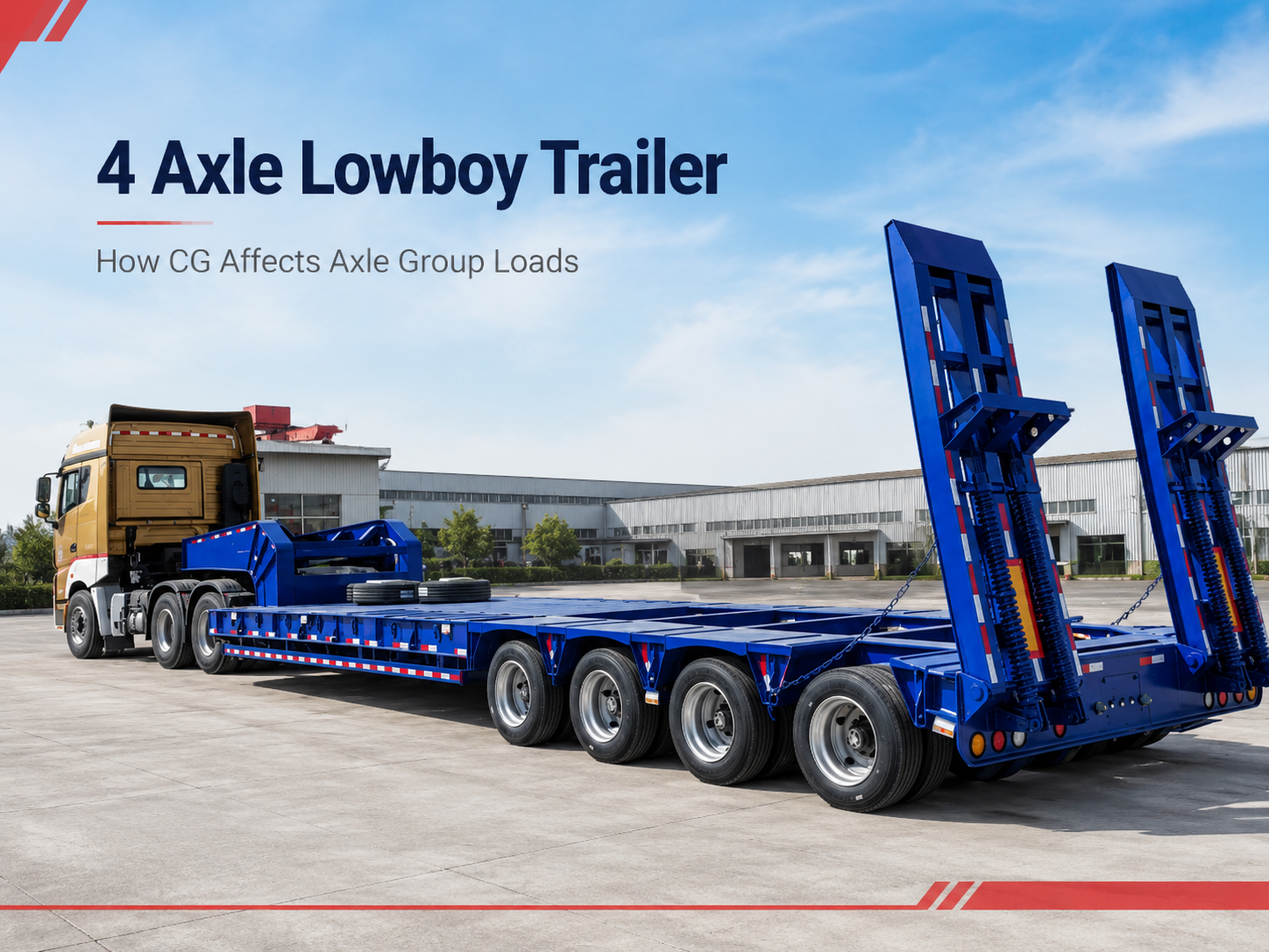
4 Axle Lowboy Trailer: How Equipment Center of Gravity Affects Axle Group Loads

A heavy excavator can sit neatly between the gooseneck and rear axle group while the combination still carries the wrong load balance. The machine may simply be too far forward or too far rearward. That is the practical problem behind 4 axle lowboy axle group load distribution: machine weight matters, but the longitudinal position of its center of gravity decides how much reaction reaches the kingpin and how much reaches the trailer axle group.
The issue often becomes visible after loading rather than before it. A tracked machine reaches the intended deck position, the tracks are fully supported, and securement access looks reasonable. Then the scale readings tell a different story. The rear group may carry more reaction than expected, or a forward correction may push too much load through the fifth wheel.
Moving the machine can correct the balance. However, the direction and approximate amount of movement should be understood before another loading cycle begins. Otherwise, several slow repositioning attempts may solve one axle problem while creating another.
A better approach connects machine weight, equipment center of gravity, kingpin position, axle-group geometry, tractor dimensions, and actual scale readings. The result is not a universal loading position. Instead, it is a repeatable method for finding and verifying a position for the real tractor, trailer, machine, and route.
The useful distinction is simple
Total trailer capacity and load distribution answer different questions. A combination can remain below an overall payload figure while the kingpin, tractor axles, trailer axle group, tires, suspension, or another component carries an unacceptable reaction.
Why Equipment Center of Gravity Matters on a Four-Axle Lowboy
Heavy equipment does not send its entire operating weight through the geometric center of its tracks or tires. Instead, the combined mass can be represented by a center of gravity, or CG. For longitudinal load planning, the important question is where that point lies between the trailer’s main support reactions.
An excavator makes the distinction easy to see. The undercarriage may appear almost symmetrical, while the engine, counterweight, boom, arm, bucket, fluids, and rotating upper structure concentrate mass elsewhere. Similarly, a bulldozer with a rear ripper does not necessarily balance at the midpoint of its track contact length.
Therefore, visual centering is not enough. Two machines can occupy similar deck space yet produce noticeably different kingpin and rear-group reactions. Even the same machine can behave differently after an attachment change or a different transport orientation.
On a semi-trailer, the main longitudinal support areas are the kingpin connection and the trailer axle group. As the equipment CG moves toward the rear group, a larger share of the machine-induced reaction generally reaches that group. Meanwhile, the kingpin share falls.
Moving the machine forward reverses that relationship. More reaction travels through the kingpin, while less remains at the trailer axle group. The equipment has not become lighter. Only the way its weight is shared has changed.
A lowboy trailer provides the low loading platform used for many construction, mining, infrastructure, and industrial machinery movements. In this load-planning problem, however, deck height or general trailer selection is not the main decision. The critical question is where the machine’s CG sits after loading.
The midpoint of the tracks is not automatically the CG
Track contact length remains useful because it shows where the machine physically bears on the deck. However, the center of that footprint should not automatically become the assumed balance point.
A machine with a large rear counterweight may have its CG well behind the footprint midpoint. In another configuration, a forward working attachment may move the balance point in the opposite direction. Consequently, machine orientation on the deck can affect reaction distribution even when the visible footprint changes very little.
A four-axle group is still more than one number
A simplified static calculation can treat the four rear axles as one combined support reaction. That is useful during early positioning. Still, the combined group reaction does not prove that each axle carries exactly one quarter of the total.
Suspension geometry, equalization, chassis deflection, axle spacing, tire condition, ride height, and the weighing surface can influence actual axle reactions. Therefore, group-level calculation is the first screening step rather than the final proof.
Gather Machine Weight and Center-of-Gravity Information
Load planning should begin before the machine approaches the trailer. First, the transport file needs a weight that represents the equipment configuration that will actually travel.
A model designation alone may not provide that answer. Attachments, counterweights, protective structures, track options, fuel condition, tools, and working equipment can change the transport mass. Consequently, a base specification and an actual loaded machine may not describe the same condition.
Record the configuration, not only the machine model
Actual transport weight
Use reliable data for the machine as transported. A specification that excludes an installed attachment should not silently become the loaded weight.
Longitudinal center of gravity
Record the CG from a clearly defined machine datum. A distance such as “from the front” is incomplete unless the physical reference point is identified.
Track or wheel footprint
Contact length and width connect the engineering CG position with a physical location that can later be reproduced on the deck.
Transport orientation
Note counterweights, boom or attachment position, rotating structures, and which end of the machine faces forward.
Separately carried items need their own place in the calculation. A bucket, counterweight, tooling package, or other component at the rear of the deck creates a different weight moment from the same component positioned close to the kingpin.
Keep weight uncertainty and CG uncertainty separate
A measured machine weight does not automatically establish the CG. Likewise, a manufacturer CG drawing cannot correct a weight value that no longer matches the transported configuration.
When reliable CG information is unavailable, an estimate may help compare early loading positions. However, the transport record should identify the assumption clearly. A track midpoint used for an initial calculation should not later appear as confirmed manufacturer data.
When either uncertainty could materially affect legal axle loading or an engineering limit, better data, weighing, or qualified technical review should follow. Extra decimal places cannot make an uncertain input more accurate.
Map the Deck, Kingpin and Axle-Group Reference Points
Once the machine data is usable, the trailer needs one consistent longitudinal reference system. The important points are the kingpin centerline, the effective center of the four-axle group, and the machine CG after loading.
A loading yard may use convenient physical references such as a deck joint, side marker, frame transition, outrigger pocket, or edge of the lower platform. Those references are useful only when their distance from the engineering datum is known.
For example, a field note stating that the front track starts beside a particular chassis feature may help repeat a position. Still, that note alone does not reveal how far the machine CG sits from the kingpin. The loading record needs both pieces of information.
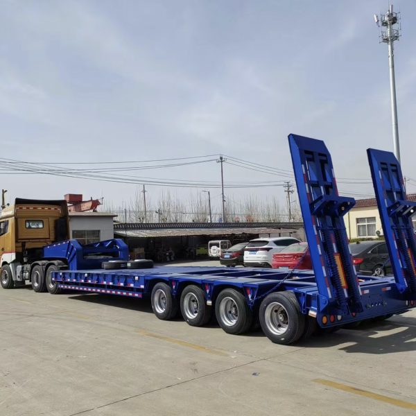
Use one coordinate system from front to rear
A simple method uses the kingpin centerline as the zero point and measures rearward. The effective axle-group center and equipment CG can then sit on the same longitudinal axis.
Another fixed chassis datum can work when the kingpin is difficult to measure directly in the loading area. However, its offset from the kingpin must remain documented so the field dimensions and engineering calculation still describe the same geometry.
Include the trailer’s empty reactions
Cargo is not loaded onto an empty mathematical beam. The trailer already places its own tare reaction through the kingpin and rear axle group.
Therefore, total trailer tare alone is less useful than separate unladen reactions. Two chassis with similar total tare can still divide that tare differently between the front and rear support points.
Useful references on one load-position sheet
- Kingpin centerline
- Effective center of the four-axle group
- Distance between those two support references
- Machine longitudinal CG location
- Forward and rear track or wheel contact points
- Location of separately carried attachments
- Empty kingpin and trailer-group reactions when available
Estimate How Forward or Rearward Movement Changes Reactions
The basic load-shift relationship comes from static equilibrium. For an initial estimate, the trailer can be treated as a beam supported at the kingpin and the effective center of the rear axle group.
Let W represent equipment weight. Let L represent the longitudinal distance from the kingpin to the effective trailer axle-group center. Finally, let x represent the distance from the kingpin to the equipment CG.
Trailer axle-group reaction = W × x ÷ L
Kingpin reaction = W − trailer axle-group reaction
These equations describe the equipment contribution only. Trailer tare and any additional cargo still need to be added separately. Even so, the relationship shows clearly what happens when the machine moves.
Move the machine forward
The CG moves closer to the kingpin. Therefore, the equipment-induced trailer axle-group reaction generally decreases.
At the same time, the kingpin reaction increases and must be carried into the tractor calculation.
Move the machine rearward
The CG moves closer to the rear group. Consequently, the trailer axle-group reaction generally increases.
Meanwhile, the machine-induced kingpin reaction decreases.
Calculate a correction before moving the machine
A first scale result may show more rear-group reaction than planned. At that point, simply asking for a small forward movement gives no indication of whether the change will be enough.
Instead, a position correction can be screened before another loading movement. If the machine CG moves by a longitudinal distance Δx, the approximate change in rear-group reaction is W × Δx ÷ L.
The kingpin reaction changes by approximately the same magnitude in the opposite direction under this simplified two-support model. Therefore, every proposed forward correction should immediately trigger a tractor-side check as well.
Multiple items need multiple weight moments
A machine may share the trailer with a bucket, counterweight, tooling, mats, or another component. Each mass acts through its own longitudinal location.
Consequently, every significant carried item should contribute its own weight moment. This prevents a smaller component placed far toward the rear from disappearing inside the main machine weight even though it still changes the rear-group reaction.
Check the Complete Tractor-Trailer Combination
A trailer-level calculation answers only part of the problem. The kingpin reaction transfers through the fifth wheel into the tractor. Therefore, moving the equipment to improve the trailer group can change both steer and drive-axle reactions.
The tractor needs its own balance model. Relevant information includes actual unladen axle weights, steer-axle position, effective drive-group center, wheelbase, fifth-wheel location, fuel condition, ballast, and any auxiliary axle arrangement.
A forward correction can create a new problem
Imagine that the first loaded reading places too much reaction on the four trailer axles. Moving the machine forward may reduce that figure. However, the same movement raises kingpin reaction.
That extra fifth-wheel load then passes into the tractor according to its own geometry. Depending on fifth-wheel position and tractor wheelbase, the drive group may become the next controlling point.
Rearward movement creates the opposite trade-off. It can reduce the machine-induced kingpin reaction while increasing the trailer-group reaction. Therefore, neither direction is automatically better.
Fifth-wheel position belongs in the load record
An adjustable fifth wheel can change how the same kingpin reaction divides between the tractor axles. A calculation prepared for one fifth-wheel position should not automatically remain valid after the fifth wheel moves.
This point matters even after weighing. The machine can remain fixed on the trailer while a later tractor adjustment changes the axle reactions ahead of the kingpin.
Legal limits and engineering limits remain separate
An acceptable road axle load does not prove that every trailer, suspension, tire, wheel, fifth-wheel, or chassis reaction remains within its engineering limit. Likewise, component capability does not establish legal compliance.
Destination-country rules may also treat axle groups differently. Axle spacing, bridge formulas, road classification, route restrictions, permit conditions, and other local requirements can change the acceptable distribution.
Therefore, the current transport authority requirements, permit conditions, fleet procedures, equipment documentation, and qualified engineering guidance should control the final decision. A universal numerical threshold should not be carried from one market into another.
The BOCA lowbed semi-trailer range provides different chassis references for heavy-equipment transport. Still, axle quantity alone cannot establish the correct equipment position for a specific movement.
Use Weighing or Engineering Review to Verify Assumptions
Calculation is most useful when it identifies a sensible first loading position. Scale readings then show whether the real combination behaves as expected.
Gross combination weight alone is not enough for this purpose. A total reading can remain acceptable while the steer axle, drive group, trailer group, or an individual axle carries too much reaction.
When weighing deserves priority
Weight verification becomes particularly important when uncertainty can materially affect legality or engineering margin. Typical triggers include:
- The longitudinal machine CG is estimated rather than confirmed.
- Actual machine weight differs from available documentation.
- Attachments or counterweights change the planned configuration.
- A preliminary axle reaction sits close to a governing limit.
- The tractor or fifth-wheel position differs from the planning model.
- Additional cargo was placed on the trailer after the first calculation.
- Permit conditions require axle or axle-group weight evidence.
- Measured reactions differ materially from the predicted distribution.
Scale setup also affects the result. Uneven approaches, wheel-height differences, suspension binding, braking forces, or incorrect portable-scale positioning can create misleading readings.
Therefore, an unexpected result should first prompt a measurement-condition check. Moving the machine in response to an unreliable reading can make the real distribution worse.
Compare the measured result with the predicted result
A scale ticket should do more than produce a pass-or-fail decision. Comparing it with the calculated reactions helps test whether the assumptions describe the actual combination.
A material difference may point to incorrect machine weight, inaccurate CG location, unrecorded cargo, an incorrect trailer reference dimension, different fifth-wheel position, outdated tare data, suspension behavior, or a scale setup issue.
When individual trailer axles behave differently from the simple group estimate, more detailed axle or wheel measurement may be needed. Dividing the rear-group total by four should not replace actual measurement where the operating margin is narrow.
Stop relying on the simplified model when the uncertainty controls the decision
Unknown structural reactions, inconsistent scale results, uncertain CG data, unusual suspension behavior, or a position that approaches several limits simultaneously should trigger qualified technical review rather than increasingly small field adjustments.
Document the Final Equipment Position Before Dispatch
Once the combination reaches an acceptable verified position, the result should become more than a remembered location on the deck. A repeatable record makes a later movement easier and prevents a rejected position from being reused by mistake.
The strongest field record connects the machine to a fixed chassis reference. For example, a measured distance from a known trailer datum to the forward track contact point can be reproduced during the next loading operation.
The engineering record can also retain the calculated CG coordinate. Together, the two dimensions connect the theoretical balance calculation with something visible and measurable in the loading area.
Photographs should explain the configuration
A useful photograph shows more than the trailer itself. Machine orientation, attachment position, track location, counterweight direction, and the relationship between the equipment and rear axle group should remain visible.
However, perspective can make a machine appear farther forward or rearward than it really sits. Photographs should therefore support fixed measurements rather than replace them.
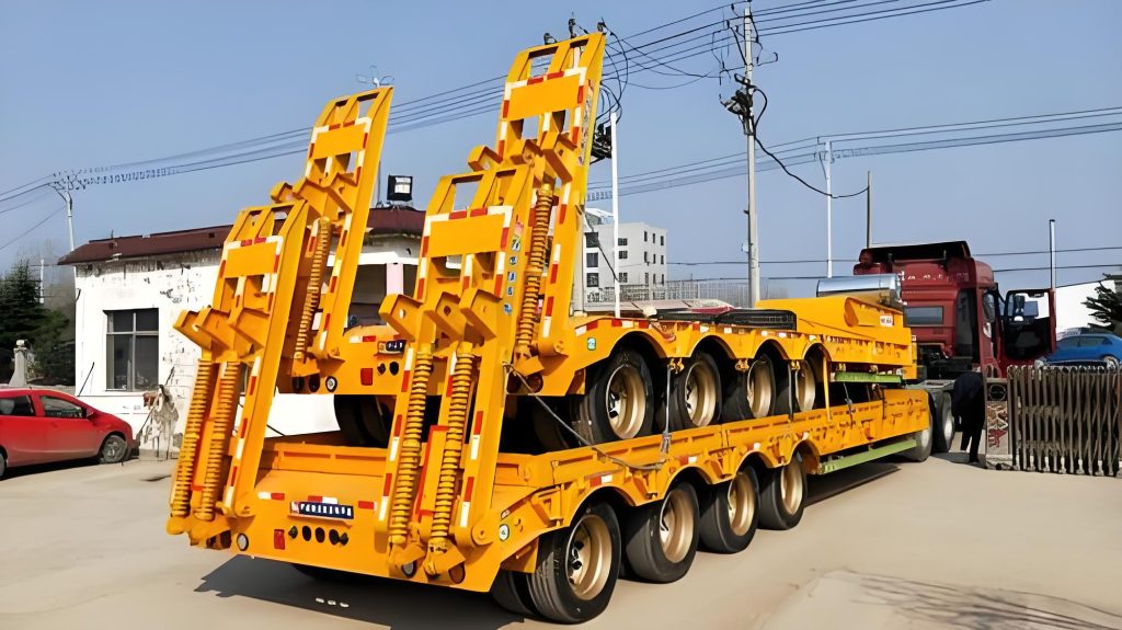
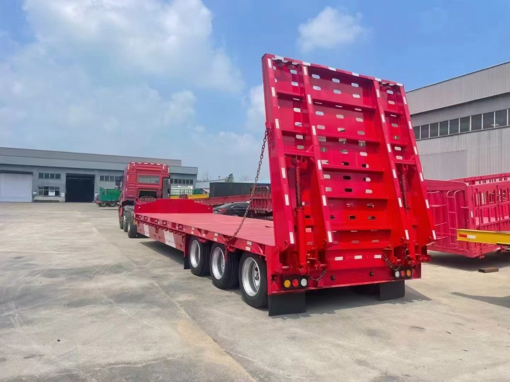
Both views show the same four-axle lowboy product rather than unrelated trailer types. The purpose is to make the lower deck, fixed chassis references, and rear axle-group relationship easier to understand from different angles.
Keep the scale result attached to the exact loading configuration
A useful dispatch file identifies the tractor, trailer, machine configuration, fifth-wheel setting, equipment orientation, and scale result together. If several positions were tested, the accepted position should be clearly separated from earlier readings.
A previous loading position can provide a strong starting point on a later trip. However, it should not become a permanent rule when the machine, tractor, trailer, attachment configuration, fifth-wheel position, additional cargo, or route requirement changes.
Final position record
- Machine identity and transport configuration
- Actual or documented machine weight
- CG source and reference datum
- Track or wheel footprint and orientation
- Measured position from a fixed trailer reference
- Tractor and trailer identification
- Fifth-wheel position used during verification
- Relevant axle or axle-group scale readings
- Route, permit, or engineering restrictions
- Photographs of the accepted transport configuration
FAQ
The correct position is the one the complete combination can support
Heavy equipment is not correctly positioned simply because it fits the deck. The longitudinal CG must create a workable balance between the kingpin and rear axle group, while the resulting kingpin reaction must also work through the tractor.
Calculations provide the first position. Scale readings test the assumptions. Finally, fixed measurements, photographs, and configuration records make an accepted position repeatable instead of dependent on visual memory.
- Confirm actual machine weight, CG information, contact footprint, attachments, and transport orientation before fixing the deck position.
- Check trailer and tractor reactions together, then compare them with current component limits and destination-country requirements.
- Record the verified equipment position, fifth-wheel setting, scale readings, and machine configuration before dispatch.
Four-Axle Lowboy Load-Position Review
Prepare the Machine and Combination Data Before Discussing Deck Position
Useful project information includes actual machine weight, available longitudinal CG data, track or wheel footprint, installed attachments, transport orientation, and clear side photographs. Trailer kingpin-to-axle geometry and unladen reactions should follow.
Tractor wheelbase, fifth-wheel position, unladen axle weights, chassis reference dimensions, destination country, planned route, and applicable axle restrictions complete the technical picture. Those inputs make a load-position discussion far more useful than a machine tonnage figure alone.
Most importantly, 4 axle lowboy axle group load distribution should be checked against the real tractor-trailer combination and applicable operating rules before dispatch. Where structural or regulatory limits remain uncertain, qualified technical review should control the final decision.