

45-50 Ft Flatbed Trailer: How to Control Deck Twist During One-Side Loading of Long Cargo
How one-side loading affects a long flatbed deck, with practical guidance on staged placement, support points, dunnage, trailer movement, and final loading checks.

A practical loading approach for long beams, pipes, fabricated sections, and project cargo when crane or forklift access is available from only one side of the trailer.
A long steel beam is waiting beside the trailer, but the opposite side is blocked by a warehouse wall. At another site, a forklift has only one clear lane between stored material and the deck. These are normal loading-yard conditions, yet flatbed trailer deck twist during one-side loading can begin well before the cargo reaches its final centered position.
Once the beam is centered, the trailer may look completely normal. The more demanding moment often comes earlier. An outer support touches first, lifting equipment begins releasing weight, and one side of the deck temporarily carries a much larger reaction than the other.
For that reason, this is not simply a question of whether long cargo fits on a 45 ft or 50 ft flatbed trailer. The useful question is how the cargo moves from lifting equipment to its intended supports without creating an uncontrolled intermediate condition.
How One-Side Loading Creates Temporary Deck Torsion
A centered vertical placement sends cargo reaction closer to the trailer centerline. A side placement does something different. The load first enters the deck away from that centerline, so one side receives more downward reaction while the opposite side carries less.
That imbalance creates deck torsion, or twisting through the trailer structure along its length. Vertical bending may happen at the same time, but the two effects are not identical. A long deck can bend under cargo while also twisting because the temporary reaction sits off center.
Long cargo can make the situation deceptively calm. A beam may touch several metres of deck, yet most of its weight may still pass through only two pieces of dunnage. A fabricated machine frame can also look broad while several narrow feet form the real load path.
Visible contact area tells only part of the story. The more useful question is where the weight actually enters the deck. Those support points determine how far the cargo reaction acts from the trailer centerline.
The temporary position can matter more than the finished position
Consider a crane lowering a long beam from the left side. At first, the crane carries nearly all the weight. The outer dunnage then makes contact while the hook still supports most of the beam.
As the hook lowers, more reaction enters that outer support. The trailer is now carrying meaningful weight even though the beam remains well away from its final lateral position. This short part of the lift can create the strongest temporary side-to-side imbalance.
A forklift creates the same problem through a different sequence. One section of the cargo may already rest on the deck while another remains on the forks. Each small lowering movement changes the share carried by the trailer.
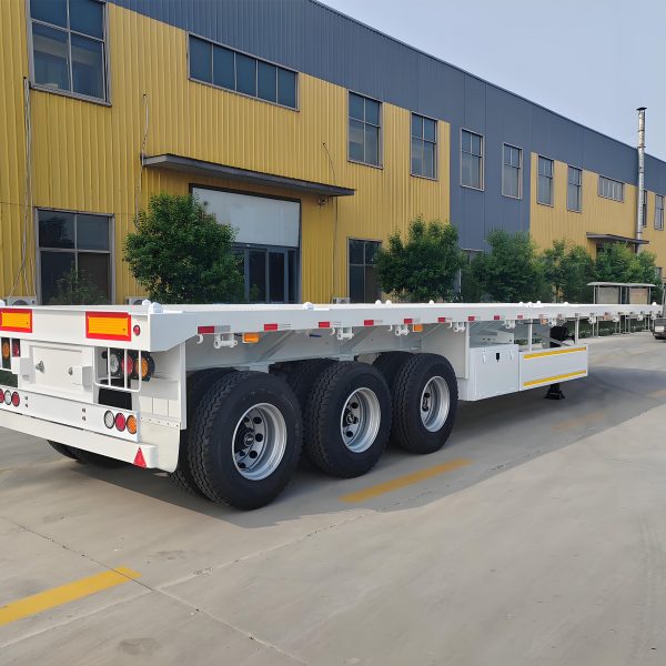
This is why trailer selection and loading access need to be considered together. A suitable flatbed trailer for long cargo provides an open working deck, but the temporary load path still depends on the site and handling method.
For a 45 ft or 50 ft trailer, deck length affects where long cargo and its supports can be positioned, but length alone does not establish resistance to twisting. The chassis sections, crossmember arrangement, support locations, and suspension also matter. Before choosing between configurations for repeated one-side loading, ask the manufacturer to review the intended temporary contact points and concentrated reactions rather than relying on overall payload capacity alone.
Some elastic movement can occur as a steel structure receives changing loads. That alone does not prove damage. What matters operationally is whether movement remains progressive, understandable, and consistent with the changing cargo position.
A sudden local change tells a different story. Visible permanent set, sharp structural movement, unstable support contact, or unusual metallic noise should stop the sequence. Continuing simply because the cargo will eventually be centered can hide a condition that needs competent technical assessment.
Why Ground Level and Trailer Support Change the Starting Condition
A trailer does not enter every loading job from the same starting condition. One operation takes place on a level concrete logistics yard. Another happens beside a fabrication workshop where repaired pavement, drainage channels, and soft shoulders sit only a few metres apart.
That difference matters during one-side loading. If the ground beneath one side settles at the same time as cargo reaction increases, the resulting lean can look like structural twist or add to the movement already taking place.
The useful starting point is simple: know how the unloaded trailer sits before the lift. General side-to-side attitude, suspension position, wheel contact, tractor connection, and approved support condition provide a baseline for later comparison.
A familiar yard can still create a poor starting condition
Imagine a loading bay used every week. The surface looks sound from the cab, but repeated forklift traffic has weakened one pavement edge. The trailer parks with its loading side close to that damaged strip.
Nothing appears unusual while the deck is empty. Once a long section begins entering from the same side, a tire or support area settles slightly. Now the deck position is changing for more than one reason.
Ground condition belongs in the loading assessment rather than being treated as a separate site issue. Crane support areas, forklift routes, tractor wheels, trailer tires, and any approved temporary support all rely on stable ground.
The cargo information should be equally clear before lifting starts. Weight, any reliable center-of-gravity information, the intended first contact point, final cargo position, and planned dunnage locations all help explain how reaction should move across the trailer.
Cargo shape also changes the picture. A bundled pipe load, rigid I-beam, and machinery skid can have similar total weights while placing very different reactions into the deck. One may share weight across several contacts, while another relies on only a few small load-bearing areas.
Trailer support should remain within the approved operating arrangement. Landing gear should not become an improvised structural prop simply because the loading side is difficult to access. The same principle applies to additional temporary supports.
Where axle limits, route permits, bridge restrictions, legal overhang, or unusual structural reactions affect the operation, applicable destination-country rules and qualified technical advice should govern the final plan. Visual judgment alone cannot replace a required engineering or compliance check.
Why the Full Crane or Forklift Path Matters
A common planning mistake is to focus on where the first contact will happen. In a restricted yard, the more difficult question is what happens immediately afterward.
A crane may easily reach the outside edge of the deck but have poorer geometry once the beam needs to move inward. A forklift may enter the loading lane without difficulty and then discover that there is not enough room to turn, withdraw, or make the second movement.
A useful loading path considers the entire move. It begins with cargo fully supported by the handling equipment, passes through first contact and partial weight transfer, and finishes only when the cargo rests on its intended transport supports.
Plan somewhere safe to pause
The best intermediate position is not necessarily halfway across the deck. It is a position where the cargo remains stable, the lifting equipment still has useful control, and the trailer response can be observed before more weight transfers.
This matters beside warehouse walls, port infrastructure, fabrication lines, and stored materials. Limited working space can turn a normal lift into a sequence where every metre of lateral movement changes equipment reach and operator visibility.
Crane work also needs control over cargo orientation. A long beam can rotate as sling tension changes. If one end moves unexpectedly toward the trailer edge, the intended support point can change before the loading team has time to react.
Forklift loading brings another issue. Once part of the load reaches the deck, the forklift and trailer share the reaction. The balance can change quickly with a small lowering movement, particularly when one support touches before the others.
Clear communication becomes especially valuable at that moment. One agreed signal should control whether the equipment lowers, holds, lifts again, or repositions. Several competing instructions make an already changing load path less predictable.
A simple site sketch can often expose these problems before the lift. Trailer centerline, cargo direction, first contact, intermediate support, equipment approach, and major obstructions are enough to show whether the proposed sequence remains practical from beginning to end.
For repeat operations, those site details also support a more useful discussion of flatbed semi trailer configuration. Deck length matters, but loading access and cargo reaction matter just as much when the same site handles long material every week.
Why Staged Placement Gives Better Control During Weight Transfer
In a busy yard, putting the cargo down in one movement can look efficient. The crane already has the beam under control, the deck is clear, and the final position is only a short distance away.
The problem is the speed at which trailer reaction can change. One moment, lifting equipment carries nearly the entire load. A few seconds later, an outer support may carry a large share while the cargo remains well away from the centerline.
Where the approved handling plan permits it, staged placement can make that transition easier to observe. The cargo first makes controlled contact while the crane or forklift still carries part of the load. Further weight transfer should occur only when the support condition and the equipment’s remaining control are confirmed.
If the approved lifting or positioning method allows, the cargo can be repositioned inward before further significant weight transfer. Staging provides points at which to check the trailer response; it does not guarantee a lower peak torsional load. The cargo must not be pushed or slid across the deck without an engineered, controlled method.
Avoid turning placement into an uncontrolled slide
A long beam sitting heavily on timber may resist sideways movement at first. Additional pushing force can then create a sudden breakaway when friction changes. Cargo position and deck reaction may change at the same moment.
Very low friction is not automatically better. A load that moves too freely can accelerate across its supports or pass the intended lateral position. The objective is predictable movement rather than the lowest possible resistance.
Rollers, skates, guides, or specialised positioning systems may form part of an approved method. Improvised devices, however, can introduce another pivot point or an uncontrolled direction of travel.
At an intermediate pause, the cargo should be stable, the trailer response should still match the expected load transfer, and the next movement should not create a larger unsupported offset.
If one of those conditions is unclear, continuing simply because the final position is close adds unnecessary uncertainty. Holding the cargo in a controlled state gives the operation a chance to correct the support arrangement before the trailer accepts more weight.
How Support Points, Overhang and Dunnage Change the Load Path
Long cargo often looks better supported than it really is. A beam may extend across most of the trailer while only two or three pieces of dunnage carry the actual reaction. That difference between visible length and real support points is central to deck-torsion control.
Support locations should follow the structure of the cargo. With a straight steel beam, suitable load-bearing areas may be obvious. With machinery frames, fabricated assemblies, or prefabricated structures, the true support path can be less visible.
Temporary dunnage can make one-side loading much easier when it creates a deliberate intermediate position. It provides lifting clearance, establishes a known point of contact, and prevents the cargo from simply landing against the outer deck edge.
Placement still matters. Moving temporary support farther outward simply because it is easier for the forklift to reach can increase the distance between cargo reaction and trailer centerline. Dunnage helps when it controls the load path, not merely when it keeps steel away from the deck.
Small height differences can change the whole reaction pattern
Three timber blocks beneath a long fabricated section can look equal from standing height. Once the cargo lowers, however, the outside block may touch first because it sits slightly higher.
For a short period, that one point can carry much more trailer reaction than expected. The remaining blocks only begin sharing weight after the structure settles farther.
Dunnage condition deserves attention before lifting. Split timber, crushed corners, contamination, unstable seating, or mixed block heights can all change when and where the cargo makes effective contact.
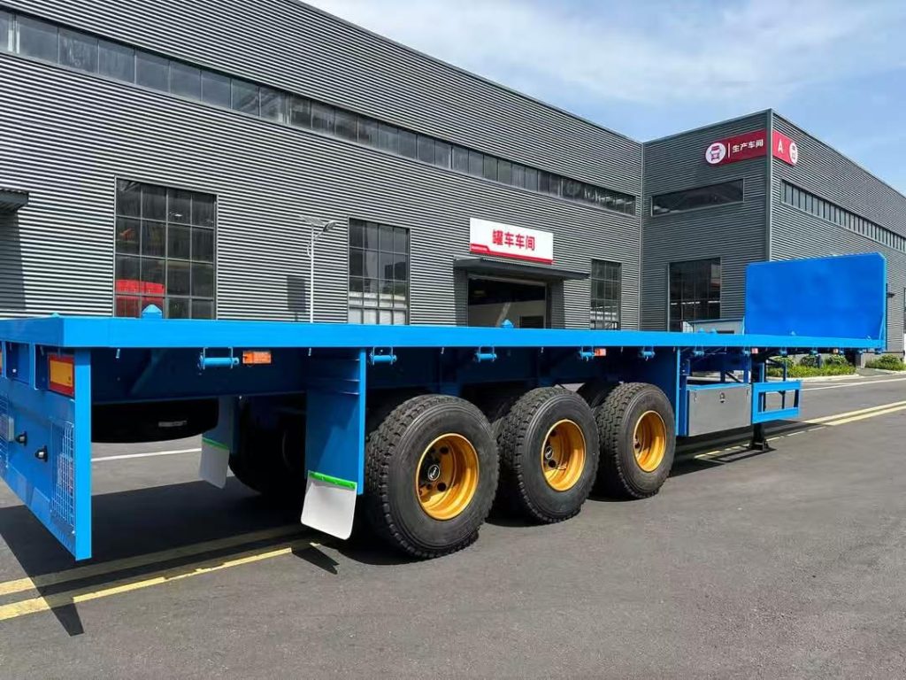
Overhang adds another layer. During an intermediate position, a long component may extend far beyond the front or rear of the trailer while sitting on only a few supports. The free length can increase leverage around those contact points.
Cargo center of gravity is more useful than visual symmetry alone. A fabricated structure carrying equipment near one end may create very different support reactions from a plain beam of the same overall length.
The same logic applies to temporary and final supports. A point that works well for receiving the load from a forklift may not be the correct transport support. The sequence should allow reaction to move from the temporary position into the final arrangement without an abrupt change.
To assess a proposed intermediate position, identify the vertical reaction entering each support and its lateral distance from the trailer centerline. For a single equivalent reaction, force multiplied by that offset describes the associated eccentric moment; it is not a trailer load rating or a stand-alone safety calculation. Multiple contact points and the chassis, suspension, and tractor support conditions require a configuration-specific review. For recurring one-side loading, ask the manufacturer to confirm the relevant chassis and crossmember details, allowable local support reactions, and whether the proposed temporary loading positions are acceptable.
No universal dunnage spacing or overhang figure suits every operation. Cargo structure, trailer design, support reaction, route requirements, and the approved handling plan should determine the final arrangement. Unusual concentrated reactions deserve competent engineering review rather than an assumed rule of thumb.
What Deck Movement Looks Normal — and When to Stop
Once cargo begins touching the trailer, observation becomes more useful than assumptions. The objective is not to treat every visible movement as a structural defect. Instead, the loading team should watch whether the deck, supports, suspension, and cargo continue behaving in a way that matches the planned transfer.
A safe view along a straight deck edge can reveal developing twist better than standing close to one small area. Another position may offer a clearer view of dunnage and suspension response. Observation should never require entry into a swing, crush, or pinch zone.
During a controlled side placement, lateral difference may increase as an outer support accepts more reaction. As the cargo moves inward, that difference should move toward the expected final loaded condition.
The direction and speed of movement matter
A gradual change while eccentric reaction increases is very different from a sudden drop on one side. Rapid movement may come from dunnage failure, ground settlement, cargo shift, suspension response, or another unexpected change in the support path.
Continued movement after the cargo stops also deserves attention. If the deck keeps changing position while lifting equipment holds steady, the source of that movement should be understood before the next stage.
Suspension behavior can complicate the picture. Mechanical and air suspension systems respond differently as side-to-side reactions change. Adjusting suspension simply to make the deck look level can hide the actual loading condition.
Tire contact provides useful context but does not prove that load distribution is acceptable. All tires may remain on the ground while the deck and suspension still carry a meaningful lateral imbalance.
For repeat loading jobs, photographs from consistent safe viewpoints can provide useful context. A strong record shows the deck line, cargo position, support locations, and suspension area together rather than relying on isolated close-ups.
Those records can also improve later planning. If the same beam family, crane position, and yard are used repeatedly, comparing the actual support path with previous operations may reveal where the loading sequence needs to change before another lift begins.
Final Checks Before Securing and Dispatch
The cargo reaching the middle of the deck does not automatically end the loading check. The final condition becomes meaningful after the crane or forklift releases its remaining reaction and the cargo rests fully on the intended transport supports.
Start with the actual cargo position. Visual centering across the width is useful, but longitudinal position matters as well. Several small lift-and-set movements can move a long beam farther forward or rearward than originally planned.
Then look at the intended supports. A dunnage block that still moves freely may not be carrying meaningful reaction. A heavily crushed or displaced block can indicate that one location has accepted more load than expected.
Compare the loaded trailer with the starting baseline
The trailer should now be viewed from the same general positions used before loading. The aim is not to make the loaded deck look identical to the empty trailer. The aim is to understand the final change.
If one side remains unusually low, several explanations may be possible. Cargo center of gravity may not sit where expected. One support may be higher, the ground may have settled, or suspension response may differ from the starting condition.
That cause should be understood before cargo restraints are tensioned. Chains, straps, binders, and other restraint systems belong to the transport stage. They should not be used to pull an unstable support arrangement into a position that merely looks acceptable.
Temporary loading material also needs a clear final status. Dunnage intended for transport should remain stable and correctly seated. Material used only to create an intermediate loading position should be removed when the approved transport arrangement does not require it.
Axle distribution needs separate confirmation. A long cargo item can appear well centered laterally while its longitudinal position still produces an unsuitable axle reaction. Required weighing, calculations, permits, and legal checks should follow the applicable transport plan.
The final walk-around should focus on what changed during loading. Deck alignment, support contact, dunnage condition, cargo stability, suspension attitude, wheels, and any area that produced unusual movement deserve another look.
If visible permanent deformation remains after cargo is repositioned or removed, the trailer should not return to service based on assumption. A qualified trailer technician or engineer should assess the affected structure before another loading cycle.
FAQ
Practical Next Step
Match the Flatbed Configuration to the Real Loading Site
For a recurring long-cargo operation, useful planning information goes beyond trailer length. Cargo dimensions, total weight, reliable center-of-gravity information, structural support areas, loading equipment, available side space, ground condition, route environment, and destination requirements provide a much clearer basis for reviewing the trailer configuration.
Site photographs add important context. A rear view can show lateral working space, a side view can show crane or forklift approach, and a view along the deck can show where temporary and final supports are expected to sit.
- Record cargo length, width where relevant, total weight, support geometry, and available center-of-gravity information.
- Identify the intended first contact point, a controlled intermediate position, and the final transport support arrangement before lifting.
- Confirm the crane or forklift type and the usable operating space available on the loading side.
- Provide clear photographs showing loading-side access, ground condition, equipment approach, and the road or site environment.
These details provide a stronger basis for discussing a suitable flatbed configuration than choosing a deck length alone. Controlling flatbed trailer deck twist during one-side loading ultimately depends on keeping the path from first contact to final support predictable enough to observe, pause, and reassess when actual trailer response no longer matches the planned sequence.