
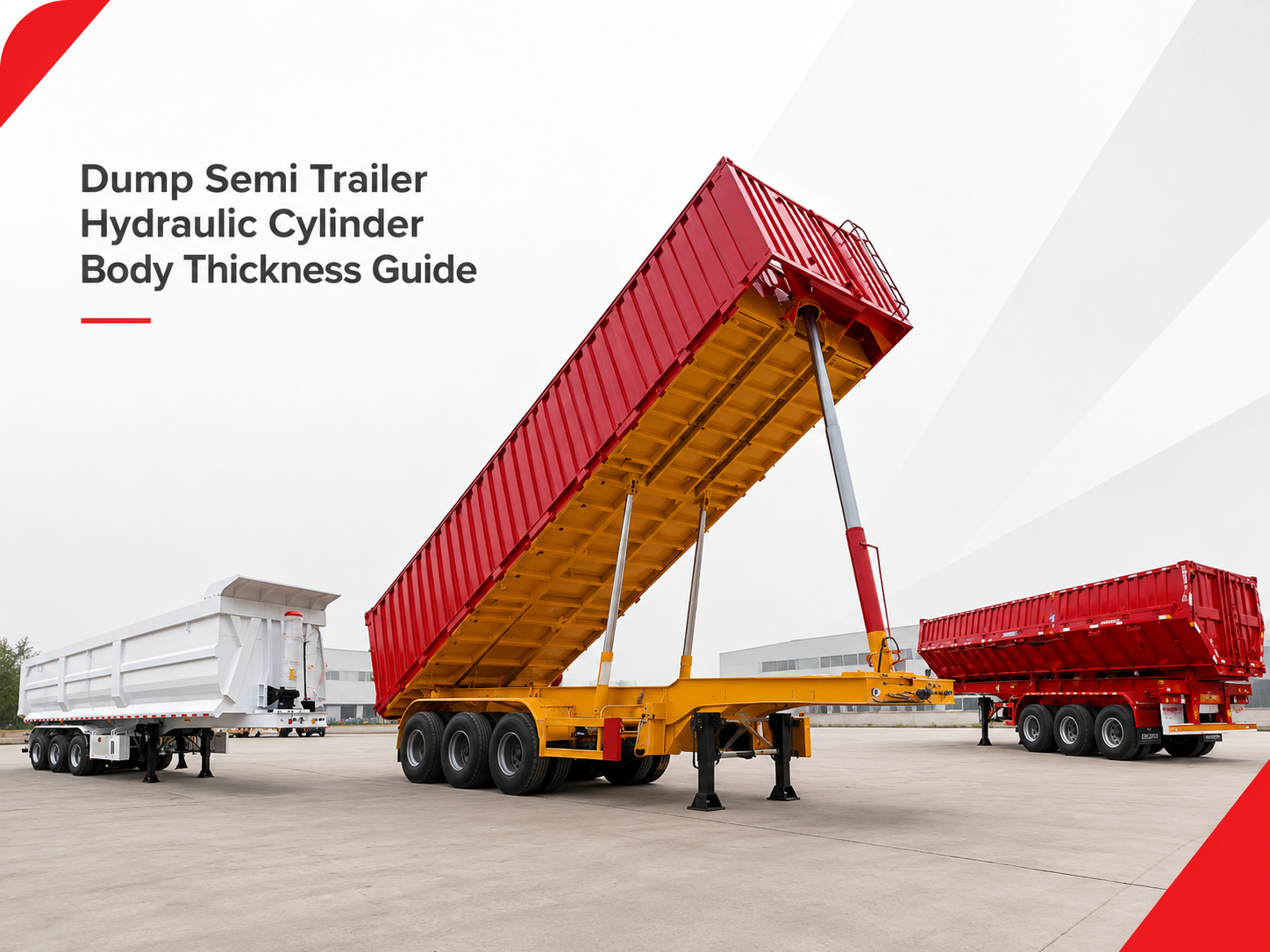
Dump Semi Trailer Hydraulic Cylinder and Body Thickness Guide

A dump trailer does not become more reliable simply because the cylinder looks larger or the body plate looks thicker. The right setup has to match lifting geometry, cargo behavior, body reinforcement, site conditions and tractor hydraulics before a technical quotation is approved.
This guide explains how to compare end dump, rear dump and side dump layouts, how hydraulic cylinder geometry affects lifting force, and how cargo density, abrasion and impact should guide the body structure.
A dump semi trailer hydraulic cylinder cannot be selected by outside size alone. Body length, hinge position, mounting angle, required stroke and tractor oil supply all change the lifting force. At the same time, cargo density, impact and abrasion determine how the floor, side walls, hinges and tailgate should be supported.
These decisions must be reviewed together. A larger cylinder cannot correct unstable ground, poor bracket geometry or a body that twists under an uneven load. Adding steel everywhere can also increase tare weight without protecting the zones that receive the most impact and wear.
A reliable specification starts with the unloading direction and actual duty. It then connects the body drawing, hydraulic circuit, site conditions, tractor interface and inspection scope. This order helps buyers compare real working conditions instead of approving a trailer from body volume, axle count or cylinder appearance alone.
Dump Trailer Types and Their Lifting Logic
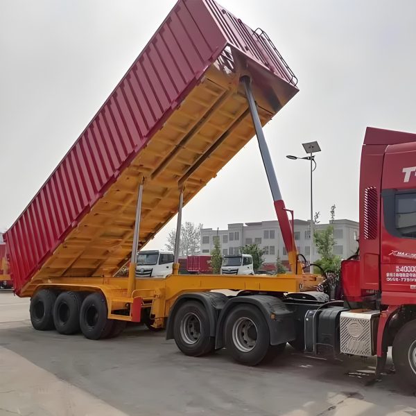
The first distinction is between lifting method and discharge direction. A front-lift system describes how the body rises. Rear dump or end dump describes where material leaves. Many rear-discharge trailers use a front-mounted lifting assembly, so the terms can overlap rather than identify completely different products.
A quotation should remove that ambiguity. The body drawing needs to show the cylinder location, hinge line, direction of rotation and tailgate movement. Once those points are clear, the load path and site requirements can be compared without relying on product names alone.

Which dump layout fits the job?
Choose an end dump direction when the site has enough rear discharge space, firm level ground and vertical clearance for the raised body. Choose a rear-dump arrangement when the project depends on tailgate-controlled rear unloading and the trailer can stay straight during tipping.
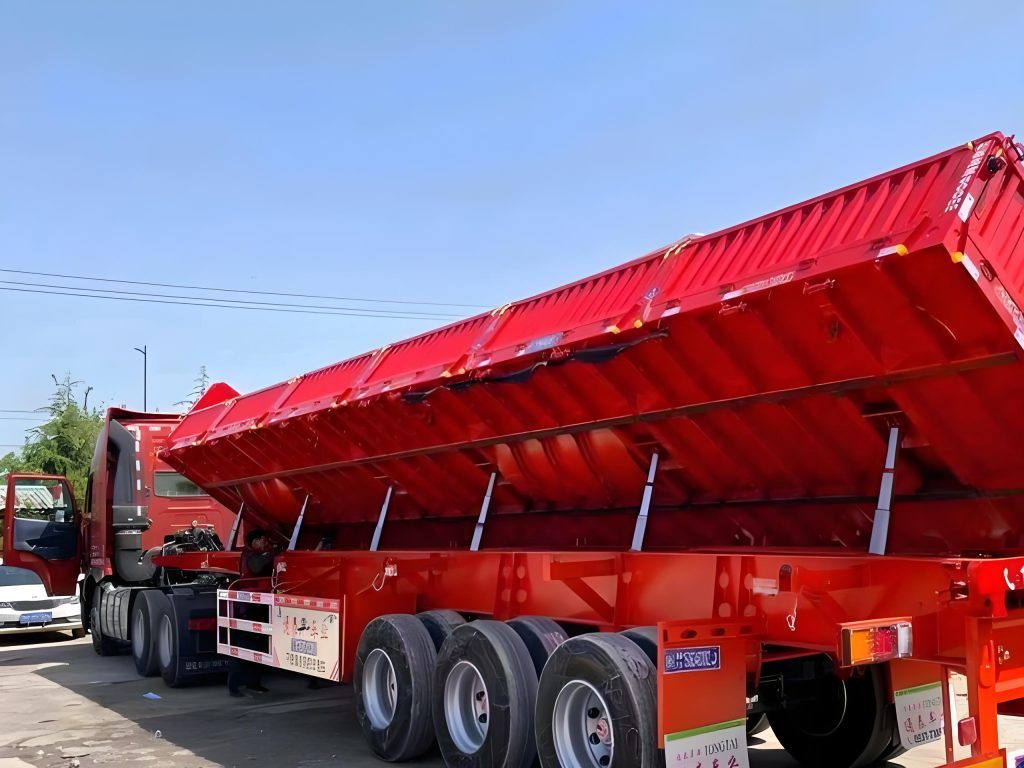
Choose a side dump when material needs to be placed along a work lane, windrow or side area, especially when rear space is limited. In that case, the tipping side needs firm support, safe lateral clearance and a frame layout that can handle torsional loading.
Each layout transfers force through a different route. Cylinder brackets feed load into the subframe and body rails. Hinges then carry the rotation reaction. A thick local mounting plate has limited value if the surrounding members cannot spread that force.
Material movement changes the load again. Dry sand may leave in a steady stream, while stone can release in pulses. Long construction debris may bridge across the body. The arrangement must suit both the intended motion and the actual discharge behavior.
Front-Lift Cylinder vs Side-Dump and Rear-Dump Arrangements
A useful comparison examines the whole movement rather than visible cylinder size. Starting angle, lever arm, stroke and hinge position control the force curve. Cargo release and available space determine whether that movement remains suitable at the site.
The three layouts below are decision paths, not fixed specifications. Final dimensions and hydraulic values must follow the agreed drawing, cargo information and tractor supply.
Main questions
- Can the initial angle provide enough starting force?
- Where is the cargo centre relative to the rear hinge?
- Is there enough vertical clearance for the raised body?
- Can the front mount transfer force into the subframe?
Main questions
- Does the body rotate smoothly through the full side path?
- Is the hinge line aligned and fully supported?
- Can the crossmembers resist torsional loading?
- Is the selected discharge side clear and firm?
Main questions
- What exact hinge and lifting geometry is proposed?
- When and how does the tailgate release?
- Can material leave without striking nearby structures?
- Can the combination remain straight while tipping?
Starting force and changing lever arms
At the beginning of a front lift, the cylinder may work at a less favourable angle. High force can be required before the body moves far. As rotation continues, the lever arm changes and the required force can fall. A forward-heavy load or sticky material can interrupt that expected pattern.
A side-dump system follows another force curve, but the same principle applies. Poorly positioned mounts can require excessive pressure or create abrupt movement near the end of the stroke. Cylinder and hinge coordinates should therefore be reviewed as one mechanism.
Alignment is equally important. Bracket error, frame twist or worn hinge bushings can push the rod sideways. That side load increases seal wear and may distort the mounting structure. Smooth axial movement depends on both accurate fabrication and regular maintenance.
Matching Cylinder Geometry to Body Size and Working Load
Cylinder selection should begin with the body drawing and a realistic load description. Body length, hinge location, mounting height and target tipping angle establish the movement. Cargo position and density establish the working moment.
A longer body can move the load centre farther from the hinge. Even so, length alone does not define the demand. Dense material placed close to the front wall may create a harder start than a longer but evenly distributed load.
Stroke and tipping angle
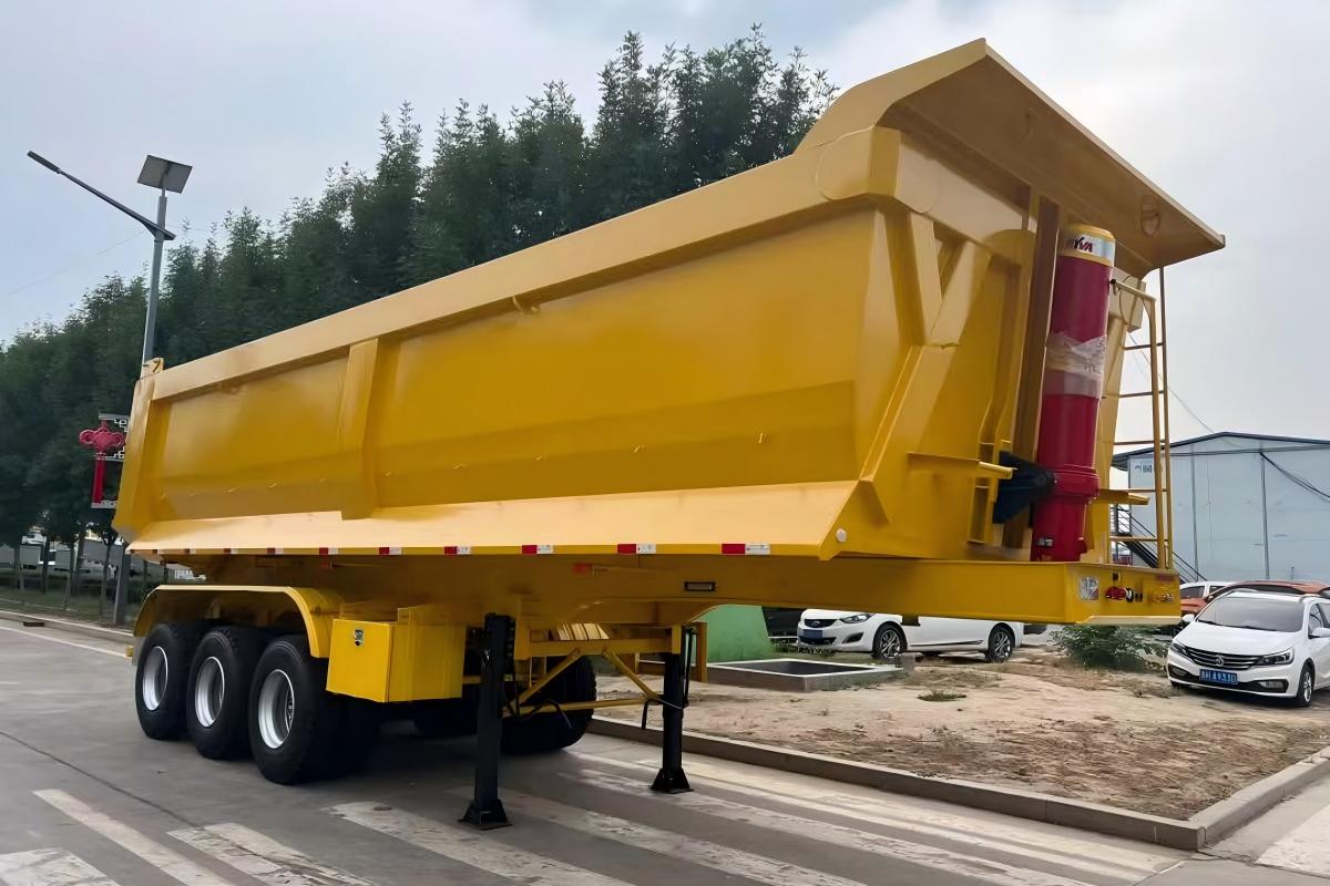
Stroke must create enough body rotation for the intended cargo to release. More stroke is not automatically better. A very high angle raises the centre of gravity, exposes more cylinder length and can complicate hose movement. Too little angle may leave wet fines or sticky waste inside the body.
The target angle should follow material flow and site stability. Dry aggregate may begin moving early. Wet clay can remain attached to the floor. Construction debris may need more tailgate clearance while still presenting a bridging risk.
Pressure, flow and cycle control
Hydraulic pressure produces lifting force, while oil flow influences movement speed. Both depend on the tractor pump, valve, reservoir, hoses and couplings. A cylinder that requires more pressure than the tractor can supply will not provide the intended lift.
Very high flow creates another problem. The body may rise too quickly, stop sharply or generate more heat. Restrictions in hoses and connectors can reduce usable flow. For that reason, the complete oil path should be reviewed instead of treating the cylinder as an isolated item.
Working load and duty cycle
The working load should allow for reasonable loading variation. Loader buckets are not always placed perfectly. One cycle may leave more material near the front or one side. The agreed design needs a clear operating range for this normal variation.
Tipping frequency affects the system as well. Repeated short cycles create heat and fatigue. Occasional unloading may reduce thermal demand, although heavy impact can still dominate. Cycles per shift, ambient temperature and route pattern belong in the technical brief.
How Cargo Density and Abrasion Affect Body Thickness
Dump body thickness should follow the cargo, loading method and support layout. Density determines how quickly the operating mass is reached. Abrasion removes material over repeated cycles. Impact depends on particle size, shape and drop height.
These factors should be separated during specification. Dense material may reach the permitted mass before the body appears full. Lower-density waste may fill the body while still creating severe local impact from concrete or steel pieces.
Density is not the same as volume
Body volume describes available space, not the allowed working mass. Wet sand, ore and heavy aggregate may reach a high mass at a lower fill level. Moisture can also change density between seasons or between loads.
The quotation should state the material name and a realistic density range. When exact data is unavailable, measured loads and operating records can support the discussion. Final limits still need to follow route, axle and destination requirements.
Abrasion and impact create different wear zones
Abrasive material often thins the floor, lower walls and tailgate edge over time. Impact produces dents or cracks near the loading zone. Large rock can combine both effects, while fine sand may cause gradual surface loss.
Wear rarely develops evenly. Local liners or replaceable protection may suit some duties, subject to the final design. Adding protection everywhere can increase tare weight and make future repair more complex.
Thickness must be matched with support
Plate thickness alone does not define body stiffness. Crossmember spacing, side-wall folds, posts and rail sections determine how the plate is supported. A well-supported floor can behave differently from a thicker plate spanning a larger gap.
A balanced design places material where impact and wear occur while controlling unnecessary tare weight. Since material grades and structures can vary, every final plate and reinforcement choice should appear in the approved specification rather than being assumed from an application label.
Floor, Side Wall, Hinge and Tailgate Reinforcement
A dump body behaves as one connected structure. The floor receives loading impact and sliding wear. Side walls resist outward pressure. Hinges guide rotation, while the tailgate retains material during transport and manages discharge at the site.
Floor and crossmembers
Support spacing controls local deflection. The loading zone may need different protection from the rear sliding zone. Dents and rough transitions can trap sticky cargo.
Side walls and top rails
Wall stiffness comes from plate shape, posts and rails. Taller walls add volume but raise the centre of mass and increase demand during uneven loading.
Hinges and cylinder mounts
Brackets should transfer force into strong rails and crossmembers. Thick isolated plates can move stress to their edges when nearby members remain flexible.
Tailgate design and discharge sequence
The tailgate must hold material during transport and open at the correct point in the tipping cycle. Uneven locks can twist the gate. Fine material can enter latch areas, while large stone can strike the rear structure during release.
Gate clearance should reflect particle size and bridging risk. A layout suited to dry sand may not suit mixed debris or large rock. The opening sequence should prevent cargo from remaining trapped while the body continues to rise.
Service access matters too. Hinge pins, bushings and locks need inspection, lubrication and cleaning. Packed material should not hide retaining devices or prevent full closure.
Broad phrases such as “heavy-duty body” or “reinforced chassis” do not define the structure. A useful quotation identifies the protected zones, support members and intended load path. This makes production review and later inspection more objective.
Mining, Sand, Gravel and Construction Waste Applications
Application names provide only a starting point. Mining work can involve fine processed ore, overburden or blasted rock. Construction waste may include soil, concrete, brick, timber and steel in the same body. Each combination creates a different wear and discharge pattern.
Mining and quarry work
Mining dump trailer service often combines dense material, rough roads and repeated loading impact. Fine ore may create strong abrasion. Larger rock adds concentrated impact at the floor and tailgate. Route quality determines how much frame twist and vibration the trailer sees between loading and discharge.
Short site routes can produce many tipping cycles and greater hydraulic heat. Longer routes shift attention toward axle loading, braking and fatigue. The operating pattern should be stated instead of relying on the general phrase “mine use.”
Sand and gravel
Dry sand may release quickly, but fine grains enter small gaps around hinges and locks. Wet sand becomes denser and may stick to the floor. Gravel creates more impact and can wear the rear edge as material slides out.
For these duties, smooth internal surfaces, tailgate fit and regular cleaning can matter as much as extra steel. Loading level should follow measured mass rather than visual volume alone.
Construction waste
A construction waste trailer faces irregular contact points. Concrete pieces can dent the floor. Long timber or steel can bridge near the tailgate. Wet or contaminated material may also increase corrosion and cleaning demands.
Sorting and controlled loading reduce these risks. Typical maximum piece size, moisture and drop height should be recorded. When several materials will be carried, the most demanding normal duty should guide the body discussion.
Related Reading
Broader Dump Trailer Project Selection
For axle configuration, suspension, route conditions and wider project fit, the related article provides the broader procurement context. This guide remains focused on cylinder geometry and body structure.
dump semi trailer buying guideStability, Ground Conditions and Tractor-Hydraulic Matching
Tipping stability depends on the complete combination. Body height, axle support, suspension, tire contact, ground firmness and tractor alignment all affect the raised centre of gravity. Hydraulic power cannot correct an unstable surface.
Ground level and ground strength
A surface can look level while remaining soft. One wheel group may sink after the body begins to rise. That movement twists the chassis and changes cylinder alignment. Ruts, loose fill, buried trenches and stockpile edges require attention before tipping starts.
Side slope is especially important for a tall rear-discharge body. Side-dump operation has a different concern because support beneath the tipping side may weaken as material leaves. Seasonal rain should be included when ground conditions change during the year.
Tractor alignment and fifth-wheel height
The tractor and trailer should remain as straight as practical during tipping. Sharp articulation changes support geometry and can introduce lateral load. Fifth-wheel height also affects whether the trailer runs level before lifting.
Tire size, pressure and suspension condition influence that attitude. A nose-high or leaning trailer can alter axle loading and body movement. These basic vehicle conditions should be corrected before hydraulic performance is judged.
Tractor hydraulic interface
Pressure, oil flow, reservoir capacity, valve control and coupling type should match the trailer system. Existing equipment still needs inspection rather than assumed compatibility. Hose routing and oil cleanliness affect movement and component life.
When a used tractor truck is considered, pump condition, fifth-wheel height, braking connections and hydraulic controls require confirmation. The tractor and trailer should be treated as one working system.
Smooth valve response is preferable to abrupt movement. If the body stalls, leans or rises unevenly, the cycle should stop for inspection. Forcing the lift can increase damage when the true cause is sticky cargo, poor ground, hydraulic restriction or mechanical binding.
Inspection and Maintenance Points Before Operation
A practical inspection looks for changes that affect lifting alignment, oil flow or structural support. Frequency should reflect duty cycle and site severity, while the written maintenance plan remains the primary reference.
For one official safety reference, OSHA guidance on raised dump body support discusses the need for a positive means of support when workers inspect or service equipment below a raised dump body. This article is not a legal checklist, but the same principle is useful during technical review: hydraulic pressure alone should not be treated as the support method for inspection beneath a raised body.
Hydraulic system
- Leaks around fittings, valves and seals
- Cuts, abrasion, bulges or poor hose routing
- Cylinder rod scoring or contamination
- Oil level, condition and connector fit
Body and rotation points
- Cracks near mounts and weld transitions
- Loose pins, worn bushings or missing retainers
- Floor dents, wall movement or body lean
- Tailgate lock alignment and debris buildup
Vehicle and site
- Tire pressure and suspension condition
- Fifth-wheel connection and landing gear
- Ground firmness, slope and clearance
- Straight combination before lifting
Unusual movement deserves immediate attention. A cylinder bracket that shifts under load, a hinge with excessive clearance or a tailgate that closes unevenly can indicate a larger alignment problem. Lubrication cannot correct bent brackets or enlarged pin holes.
Residual material changes the next cycle. Hardened cargo adds weight and creates an uneven loading surface. Cleaning supports more predictable discharge and makes structural inspection easier.
Where site rules allow, a controlled functional check can confirm smooth lifting and lowering. The work area must remain clear. No person should enter beneath a raised body without approved support and hydraulic isolation procedures.
Information Required for a Technical Quotation
A useful quotation reduces assumptions before production begins. Body volume and axle quantity are not enough. Cargo behavior, lifting direction, site conditions, tractor hydraulics and destination requirements should be provided together.
The final offer should separate confirmed specifications from open points. Materials, dimensions, hydraulic interfaces and inspection records need written agreement. Any later substitution should follow the same approval process.
Site photos and tractor interface photos can clarify details that are difficult to describe. They do not replace measurements, but they can reveal clearance limits, connector differences and unusual loading conditions early.
Destination-country rules may affect dimensions, axle loading, lighting, markings and documents. These items should be checked locally and reflected in the signed specification. General export experience should not be treated as automatic approval for every market.
Boca Vehicle can discuss production coordination, inspection points and delivery planning through its semi trailer export service. The agreed order should still identify final materials, body geometry, hydraulic interface and acceptance scope.
FAQ
These questions cover the main long-tail decisions around lifting layout, cargo wear, body geometry and site conditions.
How should front-lift, side-dump and rear-dump systems be compared?
Start with unloading direction and available site space. Front-lift rear discharge needs vertical clearance and firm, level ground. Side dumping needs lateral clearance and reliable support beneath the tipping side.
Then compare the body drawing, mounting geometry, hinge position and tailgate sequence. Cylinder size or lifting speed alone does not show whether the system suits the body and cargo.
What cargo details affect dump body thickness?
Density, abrasion, particle size, moisture, corrosion exposure and loading impact all matter. Drop height and the distribution of each bucket also influence local floor stress.
Thickness should be reviewed with plate support, wall shape, crossmembers and tare weight. A single fixed value cannot represent every cargo and route.
Why must cylinder selection be matched to body geometry?
Cylinder angle and lever arm change as the body rises. Body length, hinge position, mounting coordinates and stroke determine the force required at each stage.
Poor geometry can require excessive pressure, limit the tipping angle or create unstable movement. Misalignment can also push side force into the rod, seals and brackets.
Which site conditions should be confirmed before choosing a dump trailer?
Confirm ground firmness, side slope, vertical clearance, lateral clearance and rear discharge space. Ruts, loose fill, trenches and stockpile edges should also be identified.
Seasonal rain can change the surface. The specification should reflect demanding normal conditions rather than one dry inspection day.
What should be confirmed before production starts?
Confirm cargo data, target load, body dimensions, lifting layout, tractor hydraulics, destination requirements and inspection points. Drawings should show cylinder and hinge coordinates.
Open items should remain clearly marked until written approval. A general product description should not replace the signed technical specification.