

Bulk Cement Trailer Slow Unloading: Moisture, Airflow and Line Blockage Troubleshooting

A tanker reaches the batching plant, connects to the receiving silo, and begins the familiar pneumatic discharge cycle. However, cement now takes much longer to move, flow pulses through the line, or the final portion refuses to clear. bulk cement trailer slow unloading is best treated as a system symptom rather than an immediate reason to add more air. The useful question is where normal performance first changes: material condition, air generation, airflow distribution, the discharge route, or the receiving facility.
Define Whether the Problem Is Slow Flow or Incomplete Discharge
A longer unloading cycle does not automatically mean cement is moving slowly through the discharge line. Sometimes most of the lost time appears before material movement begins. In other cases, the tanker empties normally until the final portion remains inside much longer than expected.
Therefore, diagnosis should start by separating the cycle into stages. Record when the air system starts, when the installed gauge begins responding, when material first reaches the receiving line, when flow becomes stable, and when it begins fading. This short timeline often narrows the problem before any component is adjusted.
A slow start and a slow finish suggest different checks
Consider an early-morning unloading at a concrete batching plant. The connections are complete and the air source is running, yet the usual material movement does not begin for noticeably longer than normal. That pattern places early attention on air generation, leakage, valve position, or an upstream airflow restriction.
By contrast, another load may start strongly and discharge well through most of the cycle. However, the last portion takes much longer to clear. In that case, uneven aeration, compacted cement, moisture-related buildup, or a local residue zone becomes more relevant.
Total unloading time alone is not enough
A cycle that became noticeably longer gives limited diagnostic value unless the extra time can be assigned to air preparation, stable material flow, or final clean-out. Stage-by-stage timing turns a vague complaint into a usable fault pattern.
Compare similar operating conditions
A reliable baseline should come from comparable work. Material source, weather exposure, loaded waiting time, hose routing, receiving silo, and site layout can all change pneumatic unloading behavior. Consequently, a cycle at one facility should not be compared casually with another using a very different discharge path.
Location history is particularly useful. If the same tanker unloads normally at two facilities but struggles repeatedly at a third, the receiving system deserves attention. Conversely, slow discharge across several sites and several dry loads points more strongly toward the trailer-side system.
The tank, pneumatic equipment, valves, aeration components, and material outlet operate as one connected system. Therefore, diagnosis should follow the physical flow path rather than begin with random adjustments.
Start With Material Condition and Moisture Exposure
Material condition deserves an early check because pneumatic discharge depends on dry powder responding predictably to introduced air. Cement does not need to become a solid mass before moisture changes its flow behavior. Small damp zones can form agglomerates, crusts, sticky residue, or local areas that no longer fluidize evenly.
Moreover, moisture can enter at several stages. Rain during loading is an obvious route, although it is not the only one. Recently washed connections, wet discharge hoses, water around access covers, condensation after temperature changes, or extended loaded storage can also deserve investigation.
Read the history of the load before blaming hardware
A practical example occurs after an overnight wait. The tanker loaded normally the previous afternoon, but rain arrived before the morning delivery. Material begins moving, then the flow becomes uneven and the final discharge period stretches. In this situation, weather and storage history are more informative than immediately assuming the air source has weakened.
Similarly, a load following recent washing deserves context. If part of the material path remained wet, localized damp cement can begin collecting around an outlet or bend. Therefore, cleaning history should sit beside mechanical inspection in the troubleshooting record.
Useful moisture clues
- Rain, high humidity, or visible moisture during loading
- An unusually long delay between loading and discharge
- Recent washing of hoses, connections, or surrounding equipment
- Water around covers, seals, caps, or stored hose ends
- Hard lumps or adhered material found after safe depressurization
- A problem that appears with one load but disappears with later dry loads
Moisture can become both a material problem and a line problem
Damp powder can resist fluidization inside the tank. At the same time, material reaching a discharge bend may compact and reduce the effective passage. As a result, an original material-condition problem can later look like a discharge line blockage.
This overlap explains why one symptom rarely proves one cause. Surging flow, for example, may appear when damp agglomerates break free. However, similar surging can result from uneven airflow or a partial obstruction that releases material intermittently.
Look for repeatability
If one suspicious load is followed by normal discharge with dry cement, a permanent hardware defect becomes less likely. If the same symptom continues across dry loads and different receiving sites, equipment-side causes move higher on the list.
Check Air Supply Without Inventing Pressure Settings
Once material condition has been reviewed, attention can move to the air source. Pneumatic unloading needs usable airflow, but a generic pressure number is not a reliable troubleshooting shortcut. Trailer configurations, air sources, controls, receiving systems, and installed components can differ.
Therefore, actual readings should be compared with the documentation for the installed equipment and with previous normal operation. A pressure figure copied from another tanker can obscure the real fault instead of explaining it.
Start with what changed from the normal cycle
If the system now takes much longer to reach its normal operating condition, inspect the air-supply side first. Leakage, reduced air-source performance, damaged flexible connections, restricted components, or incorrect valve configuration can all reduce useful airflow.
However, a rapid pressure increase with little material movement tells a different story. Downstream resistance, poor air distribution, a restricted path, or a material blockage may deserve more attention. Pressure behavior provides evidence, but it does not identify the cause by itself.
Look for lost air before assuming more air is required
An air source can continue operating while the useful airflow reaching the material falls below normal. A leaking connection, damaged flexible line, poorly seated coupling, or valve that fails to reach its intended position can consume part of the available air.
Consequently, basic inspection should come before supply changes. Visible hose condition, connection seating, leakage sounds, gauge behavior, and recent maintenance history all deserve review. In addition, any change that appeared immediately after hose replacement or valve work should be recorded.
Abnormal heat, mechanical noise, vibration, odor, or unstable air-source operation should not become part of a normal unloading routine. Instead, those signs can justify shutdown and competent technical inspection.
Trace Airflow Through Valves, Lines and Aeration Components
A healthy air source does not guarantee that air reaches the cement evenly. Therefore, the next step is to follow the air path through the actual trailer configuration. Valves, manifolds, flexible air lines, branch lines, and aeration components all influence how effectively the powder fluidizes.
This check becomes especially important when the system appears to produce air but material movement remains weak. One restricted branch can leave part of the load poorly aerated while another region moves normally.
A valve handle position does not prove a clear internal passage
A handle or actuator can appear to reach the expected position while internal movement remains restricted by wear, contamination, damage, or incomplete travel. For that reason, valve behavior should be compared with established normal operation rather than judged from the external position alone.
Operating sequence matters as well. If air reaches the wrong branch during the wrong stage, the result may resemble low air supply. Consequently, the approved procedure should be checked before parts are removed or settings are changed.
Uneven aeration often appears as uneven material movement
A familiar symptom is a short period of strong material flow followed by a fade and another surge. One possible explanation is uneven aeration. The easily fluidized region leaves first, while a compacted or poorly aerated section becomes the limiting part of the load.
Likewise, final residue location can provide useful evidence after full isolation and depressurization. Material concentrated in one area suggests a different condition from a thin, evenly distributed residue.
Trace the air path in order
- Confirm the approved operating sequence.
- Check visible air connections and flexible lines.
- Review valve movement and condition.
- Follow distribution branches where safe inspection permits.
- Compare aeration behavior with previous normal unloading.
- Inspect internal buildup only after proper isolation and depressurization.
Aeration components can lose effectiveness through contamination, damage, uneven air delivery, or material buildup. Moisture can worsen the situation because damp cement may adhere near air-distribution areas and create preferred paths around compacted material.
Therefore, normal-looking gauge behavior does not prove that fluidization is normal. Pressure response, airflow, material movement, residue pattern, valve behavior, and maintenance history should be interpreted together.
Inspect Discharge Hoses and Bends for Restriction
After the air side has been reviewed, trace the material path from the trailer outlet to the receiving inlet. A discharge line does not need to become completely blocked before unloading time increases. Partial restriction can reduce the effective flow area while cement continues moving.
In routine operations, that condition can be easy to overlook. Material is still reaching the silo, so attention remains on the air source. However, a crushed hose section, internal deformation, retained cement, restrictive bend, or buildup around a coupling can gradually make the cycle slower.
Trace the entire route instead of inspecting one hose
Begin at the trailer outlet and continue through fixed piping, transitions, couplings, flexible hoses, bends, and the receiving connection. Meanwhile, compare the present route with a known normal unloading arrangement whenever possible.
For example, a temporary construction site may place the tanker farther from the silo than the normal discharge point. Additional hose or sharper routing can change resistance. That does not prove a blockage, but the change belongs in the diagnosis.
Weak but continuous flow
Consider a partial line restriction, restrictive routing, uneven aeration, or receiving-side resistance.
Pulsing or surging flow
Inspect bends, coupling transitions, damp agglomerates, airflow distribution, and downstream resistance.
Flow stops after a normal start
A developing plug, valve problem, or receiving restriction becomes more likely. The line should not be opened while pressurized.
Only one silo causes the delay
Receiving pipework, venting, filtration, inlet condition, and site hose routing deserve investigation before trailer parts are replaced.
Flexible hoses deserve more than an external leak check
A hose can look acceptable externally while its internal passage has changed. Repeated bending, crushing, abrasion, deformation, or internal deterioration can restrict flow without creating a visible hole.
Therefore, unusual flattening, persistent kinks, distorted couplings, soft areas, rigid areas, or sections that no longer return to their normal shape deserve attention. Where the approved maintenance procedure permits, comparison with a known serviceable hose can help isolate the problem.
The receiving silo is part of the system
The tanker is only one side of the pneumatic transfer path. If the receiving system cannot accept the air-material stream normally, the resulting resistance can look like a trailer fault.
Consequently, repeated location-specific delays should be shared with the responsible facility team. Receiving inlet condition, venting, filtration, and site pipework should be checked under the facility’s approved procedures.
Use Symptom Patterns to Isolate Likely Causes
Individual symptoms overlap. Therefore, pattern recognition should guide inspection rather than replace it. The strongest diagnosis combines timing, gauge behavior, moisture history, material flow, hose layout, residue pattern, and receiving-site history.
The following patterns can narrow the next inspection without turning one observation into a final conclusion.
Slow pressure development before material moves
Begin on the air side. Leakage, reduced air-source performance, restricted components, an incorrect valve position, or damaged connections may reduce useful airflow. Meanwhile, compare the behavior with the same unit’s previous normal operation rather than an unrelated pressure target.
Normal start followed by weak flow
This pattern moves attention toward sustained airflow, aeration distribution, partial line restriction, hose routing, damp material, or receiving resistance. First verify that the air path remains stable. Then inspect the material route after safe isolation.
Strong initial flow followed by rapid decline
The easiest-moving material may leave first while a poorly aerated or cohesive area remains. Alternatively, cement can progressively collect at a restrictive bend. Therefore, later residue location and hose condition become useful evidence.
Repeated surging during discharge
Surging proves that material can move, but not continuously. A partial blockage, damp agglomerates, uneven fluidization, unstable airflow distribution, or changing downstream resistance can all create this pattern.
Recording when each surge occurs improves the diagnosis. For instance, a surge that repeatedly coincides with a change in gauge behavior suggests a different line of inquiry from random pulses with visible damp material after shutdown.
Long final discharge with obvious residue
A long tail can point toward poor aeration around the remaining cement, moisture-related adhesion, compaction after prolonged loaded storage, outlet buildup, or an internal airflow restriction. After safe depressurization, residue location provides more information than a rough estimate of its quantity.
Slow unloading only at one facility
A location-specific pattern should raise the priority of downstream checks. If several tankers also struggle at the same receiving point, the evidence becomes stronger. Nevertheless, normal trailer-side safety checks should still be completed before the receiving facility is treated as the sole cause.
Create a field record that supports diagnosis
Repeated statements that discharge is “getting slower” provide little technical value. A short, consistent record connects the symptom with the material, pneumatic system, line route, and receiving point.
- Material type and source
- Rain, humidity, cleaning, or other moisture exposure
- Time between loading and unloading
- Previous normal cycle and current stage-by-stage timing
- Installed air-source arrangement and gauge behavior
- Visible leakage, unusual noise, heat, or vibration
- Hose route, major bends, and receiving point
- Steady, weak, surging, or stopped material flow
- Residue location after safe shutdown
- Photos or site video captured from a safe position
Stop Conditions and Professional Service Checks
Troubleshooting should stop when the next check requires opening a pressurized component, forcing a valve, disturbing an unstable connection, or continuing with abnormal equipment behavior. A tight delivery schedule does not justify turning stored pneumatic energy into an improvised test method.
Accordingly, unloading should follow equipment instructions, site procedures, isolation requirements, and applicable local regulations. Internal inspection or line dismantling should begin only after the system has been fully isolated and verified depressurized.
Conditions that justify stopping instead of restarting
- A hose, coupling, valve, or pipe appears damaged.
- A connection leaks, moves, or behaves abnormally under pressure.
- Gauge behavior changes sharply from normal operation.
- Material stops and a blockage is suspected.
- Severe vibration, abnormal noise, heat, or odor develops.
- A valve requires unusual force or does not respond normally.
- Repeated restart attempts reproduce the same restriction.
- Hardened material or substantial internal buildup is suspected.
- The receiving facility cannot accept the discharge normally.
In particular, a suspected blocked hose or coupling should never be tested by loosening the connection while pressure remains. Material movement can stop while stored pressure remains in the line. Therefore, no-flow does not mean no-pressure.
Gradual deterioration also deserves escalation
A discharge cycle that becomes slightly longer every week can be easy to normalize. However, gradual deterioration provides useful evidence of increasing buildup, leakage, hose restriction, valve wear, declining aeration performance, or air-source problems.
Therefore, maintenance records should show when the change began and what work occurred around the same period. A recurring pattern gives technical personnel a stronger starting point than repeated operating adjustments.
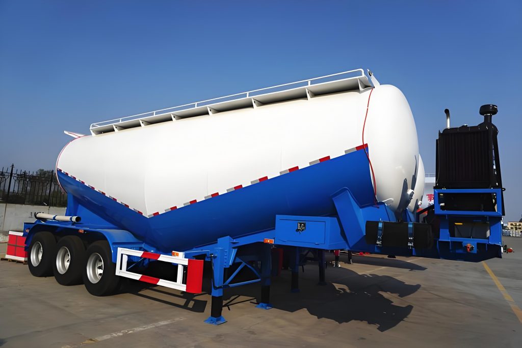
For broader dry bulk transport configurations, the BOCA dry bulk cement trailer range provides the relevant product context. However, troubleshooting should still follow the actual installed pneumatic equipment and operating conditions.
FAQ
Follow the restriction from the first changed symptom
Reliable troubleshooting begins by separating slow air preparation, weak sustained material flow, and incomplete final discharge. From there, material history, air supply, valve behavior, aeration, hose routing, and receiving conditions can be checked in a logical order.
Most importantly, bulk cement trailer slow unloading should not trigger an automatic pressure increase. Preserving the evidence and identifying the first abnormal stage usually creates a clearer path toward the actual cause.
- Record moisture exposure, stage-by-stage unloading time, gauge behavior, and flow pattern before making changes.
- Trace the air path and material path separately, then compare where the evidence overlaps.
- Escalate repeated blockage, abnormal pressure behavior, damaged connections, or unexplained deterioration instead of treating them as normal delay.
Pneumatic Unloading Review
Provide the Operating Evidence Before Changing the System
Useful technical information includes the transported material, known moisture exposure, previous and current unloading time, the stage where performance changes, the air-source arrangement, and installed gauge behavior.
The discharge route matters as well. Hose layout, major bends, receiving silo arrangement, repeated blockage locations, residue pattern, and safe site photographs or video can help separate an airflow problem from a material-path restriction.
Providing this information before technical review creates a stronger basis for troubleshooting than total unloading time alone.
Submit Unloading Details