

Dump Trailer Body Liner Wear: High-Abrasion Damage Zones

A dump body can still look serviceable from the outside while one small area inside has already absorbed hundreds of hard aggregate impacts. In quarry and construction work, dump trailer body liner wear rarely spreads evenly. Instead, crushed rock tends to punish the loading drop point, floor transitions, lower corners, and final discharge path much faster than surrounding surfaces. The useful question is therefore not whether the body looks worn overall. It is where the damage is concentrating, what part of the operating cycle creates it, and whether that local area is changing fast enough to justify closer assessment.
Why Liner Wear Is Rarely Uniform
Inside a working dump body, aggregate does not apply one type of force everywhere. During loading, individual pieces fall and strike the body. During transport, vibration lets smaller particles settle and rub. Then, during tipping, much of the load turns into a moving abrasive layer.
Consequently, several wear mechanisms can exist inside the same trailer. A front-floor patch may show repeated impact marks, while the center floor develops long polished tracks. Near the rear, meanwhile, the remaining material may create narrow grooves as it accelerates toward the opening.
This difference becomes especially clear with abrasive aggregate. Crushed stone often presents sharp fracture faces, while rounded gravel tends to roll and slide differently. Ore, broken concrete, quarry rock, and mixed demolition material can create another pattern again.
Loading practice adds another variable. A loader that releases every bucket over the same small area creates a concentrated impact history. By contrast, a broader loading pattern spreads first contact across more of the floor.
The body records how the material has been moving
Surface appearance can reveal that history. Smooth bright lanes usually suggest repeated sliding. Short deep marks point more toward impact. Narrow directional grooves often indicate hard angular pieces following a recurring discharge route.
However, the most dramatic-looking mark is not always the fastest-growing problem. A visible dent can remain stable for many cycles. At the same time, a less obvious floor transition may continue losing material because every discharge crosses the same narrow band.
For this reason, a useful inspection follows cargo movement from front to rear. The liner should be treated as several working zones rather than one large surface. That approach is particularly relevant when a heavy-duty dump trailer spends most of its operating life carrying quarry stone, ore, crushed aggregate, or similar high-abrasion material.
Read the marks as a material-flow history
Impact marks explain where stone first lands. Polished lanes explain where it moves. Narrow grooves show where hard particles repeatedly follow the same path. Separating those stages makes localized abrasion far easier to diagnose.
Map Impact, Sliding and Discharge Zones
A body inspection becomes more useful once every recurring wear area has a location name. That does not require a complicated survey. Instead, the floor and walls can be divided into repeatable zones that remain consistent from one inspection to the next.
First comes the primary drop zone. This is where the first material normally contacts the body. Around it sits the spread zone, where stone rolls or slides outward while the load pile develops.
Farther rearward, the main sliding zone becomes more important. During tipping, aggregate begins to move as gravity overcomes friction. Once the pile starts sliding, hard particles can travel across the same floor path repeatedly.
Finally, the discharge zone covers the rear floor and tailgate approach. Here, the load becomes shallower. Therefore, individual particles can remain in direct contact with the body instead of moving within a deeper mass of material.
Primary impact zone
Look for clustered dents, peening, gouging, chipped surface areas, or overlapping strike marks beneath the normal bucket or conveyor release point.
Main sliding path
Long polishing, parallel scratches, and directional grooves usually show where aggregate travels as the dump body rises.
Corners and transitions
These locations can trap fines, redirect larger pieces, or concentrate rubbing where cargo changes direction.
Tailgate approach
The final portion of the load often slides through a narrower rear path, creating concentrated abrasion near the discharge edge.
Use the direction of the marks as evidence
Direction matters almost as much as location. A dent without a trailing scratch suggests a different event from a dent followed by a long groove. Likewise, scratches that change direction near a corner can reveal where material rotates or funnels during discharge.
Overview photographs should therefore show the complete zone, while close photographs record the surface texture. Together, the two views make later comparisons much more reliable.
40 Ton End Dump Reference
Keep the Body Layout in View While Reading the Wear Pattern
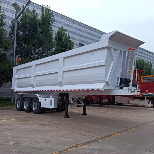
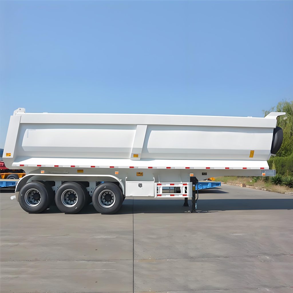
This BOCA triple-axle end dump configuration provides a relevant reference for 40-ton aggregate work. The photographs below show the complete body and rear-discharge arrangement, which helps place the inspection zones in context. They are not presented as photographs of actual liner damage; internal abrasion still needs to be judged from the working trailer itself.
Inspect the Loading Drop Point and Front Wall
The strongest local impact often begins during the first few seconds of loading. An empty body provides no layer of cargo between the incoming stone and the floor. As a result, the first bucket can leave a different signature from later buckets.
The exact drop point may also sit farther forward than expected. Material leaves a loader bucket with horizontal as well as vertical motion. Therefore, a bucket that looks centered from outside can still send the first rocks toward the front wall or one side of the floor.
Look for a concentrated field rather than one dramatic mark
Repeated loading normally creates a pattern, not just one dent. A compact oval of small strikes, shallow depressions, chipped coating, or gouging can show where the loading equipment consistently releases material. The tighter the pattern, the more stable the loading point is likely to be.
By comparison, a wide scattered field may reflect changing bucket position between cycles. Off-center wear can also indicate an angled loader approach or a loading area that places the trailer slightly differently each time.
Loading height changes impact, but it is not the only variable
Greater drop distance gives falling aggregate more opportunity to gain speed before contact. Consequently, coarse angular stone released high above an empty floor can create stronger local impact than the same material released closer to the body.
Still, loading height should not be judged alone. Piece size, hardness, bucket position, moisture, release quantity, and loading sequence all affect the final pattern. A lower bucket aimed repeatedly at one small patch can still create concentrated damage.
The front wall often explains what happens after the first strike
Large pieces can hit the floor and then roll or surge forward. In other cycles, the first bucket may contact the front wall directly before the pile settles. These two events leave different surface evidence.
Direct strikes tend to be more localized. Repeated pile contact, meanwhile, can produce broader rubbing or polishing near the lower front wall. The floor-to-wall transition deserves particular attention because aggregate can collect and move under pressure in that area.
What makes a loading-zone record useful?
A close photograph can show damage clearly while hiding the operating cause. A stronger record connects the mark with the way aggregate normally enters the body.
- Normal loader or loading equipment type
- Approximate first-bucket drop point
- Approximate release height
- Whether coarse or fine material enters first
- Whether the loading point remains centered across shifts
- Material source and general particle shape
Check Floor Transitions, Corners and the Tailgate Approach
Once the loading zone has been mapped, the inspection should follow the material rearward. The central floor may look less damaged than the front impact zone, yet every discharge cycle moves a large abrasive mass across it.
Long smooth lanes usually reveal this sliding action. Fine parallel scratches may run in the discharge direction, while deeper grooves can appear where larger angular pieces drag across the same path.
Transitions change the way aggregate moves
Any local change in contour can disturb the flow. At a floor transition, aggregate may rotate, bounce, slow briefly, or concentrate against one edge. That change often creates a narrow wear band that looks different from the surrounding floor.
Corners create another type of contact. Fine particles can remain trapped there during transport, while larger pieces may wedge temporarily during tipping. Once they break free, the same corner can experience both rubbing and sudden sliding.
Rear-floor wear can become more concentrated
Near the tailgate, the remaining pile becomes thinner. Therefore, more particles contact the floor directly instead of moving inside a deep bed of cargo. This can create a surprisingly intense final sliding zone.
Delayed release can strengthen the pattern. If damp aggregate pauses near the rear and then breaks free, local contact may be more severe than on a load that flows continuously.
Rear corners should also be compared from side to side. Persistent one-sided abrasion can suggest uneven loading, a recurring discharge path, material hang-up, or another operating condition that repeatedly directs cargo toward the same area.
Long polished lane
Usually points toward repeated sliding. Compare its width and reach with earlier photographs rather than judging shine alone.
Narrow deep groove
Often deserves a closer look at angular stone movement, particle size, and any nearby floor transition.
One rear corner changes faster
Compare loading position, discharge behavior, material hang-up, and site condition before assuming uniform abrasion.
Heavy abrasion at the final exit path
Inspect the rear floor, tailgate approach, corners, and surrounding edges together as one discharge zone.
Connect Wear Patterns to Aggregate and Loading Practice
A wear map becomes valuable once the physical marks can be connected to the haul cycle. Without that context, an inspection only records damage. With it, the same record can begin to explain why one area keeps deteriorating faster.
Aggregate characteristics come first. Hardness matters, although particle shape can be equally important. Sharp crushed stone concentrates contact along small edges, while rounded gravel tends to distribute contact differently as it rolls and slides.
Particle size changes the picture again. Large pieces can create strong individual impacts. Fine abrasive material may look less dramatic, yet it can polish broad areas or remain trapped beneath larger particles during vibration.
Moisture changes the discharge pattern
Dry free-flowing aggregate may begin moving earlier as the body rises. Damp material can remain cohesive for longer, then release in a larger mass. Consequently, two loads of the same nominal material can leave different rear-floor patterns.
Mixed material is harder to interpret. Construction debris may contain irregular pieces with sharp corners, while quarry loads can vary after a change in crushing process or source material. Therefore, the material description in a maintenance record should be more specific than simply “stone.”
Operational changes can explain sudden wear acceleration
A different loader, changed loading position, greater release height, new quarry source, or increased haul frequency can alter the wear map. When deterioration accelerates, recent operating changes deserve review before the damage is treated as random.
For example, a growing front-center impact area combined with a change in loading position points toward the loading event. In contrast, stable front wear with rapid rear-floor abrasion shifts attention toward the discharge path.
This distinction prevents ineffective corrective work. A rear sliding problem will not disappear simply because the loading point moves. Likewise, a concentrated first-bucket impact cannot be explained by tailgate appearance alone.
For broader end-dump, rear-dump, and side-dump application context, the BOCA dump trailer range provides the relevant product category. Final wear-protection decisions still need to follow the actual material, loading method, body layout, and operating cycle.
Build a Repeatable Thickness or Visual Record
One photograph records condition. A series of photographs records progression. For abrasive service, progression usually provides the stronger maintenance signal.
Start with repeatable location names. The floor can be divided into front, middle, and rear sections, then into left, center, and right zones. This creates clear references such as “front-center impact area” or “rear-right floor transition.”
Take overview and close photographs together
A close photograph can show gouging clearly while hiding its location. An overview can show location while missing surface detail. Therefore, both views should be recorded whenever a new problem area appears.
Similar viewing angles make later comparisons easier. Lighting should also be adequate because dust, wet residue, and polished reflections can hide shallow grooves or subtle surface changes.
Inspection should take place only when the body is empty, stable, isolated, and safe to access under the applicable maintenance procedure. Raised-body support, hydraulic isolation, lockout rules, site procedures, and local safety requirements remain controlling.
Thickness measurements only help when the location is repeatable
Where the liner material and inspection program support thickness measurement, the same points should be revisited during later checks. Random readings from different locations cannot establish a useful wear trend.
Ultrasonic measurement can be suitable for some metallic sections. However, calibration, surface condition, material type, coatings, geometry, and instrument limitations all affect accuracy. Qualified inspection personnel should therefore determine the measurement method.
No universal remaining-thickness limit applies to every dump body. Acceptance depends on the actual design, liner material, structural arrangement, repair history, and applicable manufacturer or engineering criteria.
A useful wear record can stay concise
- Inspection date and trailer identification
- Material carried during the inspection period
- Normal loading point and approximate drop height
- Front-wall and primary impact-zone condition
- Main sliding-path and rear-floor condition
- Corner, transition, and tailgate-approach observations
- Overview and close photograph references
- Measurement location and result, where applicable
- Change from the previous inspection
The record becomes more useful after a repair or operational change. A fresh baseline can show whether a repaired area remains stable or whether the same localized abrasion begins returning.
Likewise, if loading practice changes, the next inspection can test whether the wear pattern responds. That feedback is more useful than assuming a modification worked simply because the body looks acceptable immediately afterward.
When Localized Wear Needs Repair Assessment
Normal aggregate work will leave scratches, polish, small dents, and other signs of service. The difficult decision is identifying when one local condition has moved beyond ordinary surface wear.
Rate of change is one of the strongest clues. A broad polished area that remains nearly unchanged is different from a small groove that becomes visibly deeper between inspections.
Location matters as well. Local damage near a structural transition, attachment area, edge, or previous repair deserves more attention than superficial polishing across an open floor area.
Visible cracking or deformation changes the decision
Cracking, loose liner sections, separation, pronounced distortion, or structural movement should not be treated as cosmetic abrasion. Where body integrity becomes uncertain, operation should stop until competent technical personnel assess the condition.
Deep gouging also deserves context. A single isolated mark may have come from an abnormal rock impact, while repeated grooves can indicate an ongoing material-flow problem. Repair planning should consider both the damaged material and the event that keeps creating the damage.
Rapid local progression
A small area changing much faster than surrounding surfaces deserves closer assessment even when most of the body still looks serviceable.
Cracking beside an abrasion zone
Cracking moves the issue beyond ordinary surface wear and calls for qualified inspection of the affected structure.
Loose or distorted liner areas
Movement, separation, or loss of support should be assessed rather than treated as a normal consequence of abrasive cargo.
Damage near a transition or previous repair
These locations deserve added attention because local geometry and repair history can affect how the surrounding area behaves.
Repairing the symptom can restart the same wear cycle
A repaired front-floor patch can return immediately to the same impact environment if the first bucket continues landing in exactly the same place. Similarly, a rear-floor repair can wear again when concentrated discharge flow remains unchanged.
For that reason, technical review should include material information, photographs, loading position, drop height, operating frequency, discharge behavior, and previous repair history. That evidence gives the repair decision far more context than a single close photograph.
Welding sequence, liner replacement dimensions, reinforcement design, and minimum remaining thickness cannot be prescribed generically. Those decisions must follow the real body construction, approved procedures, manufacturer information, and qualified engineering or maintenance judgment.
FAQ
Read the wear pattern before deciding what needs attention
A useful internal inspection does not begin with a general judgment that the floor is “good” or “worn.” It begins by identifying the loading impact zone, tracing the main sliding path, and comparing the rear discharge area with earlier records.
That sequence makes localized abrasion easier to explain and easier to track. It also prevents a dramatic cosmetic mark from receiving more attention than a smaller area that is progressing much faster.
- Map the loading drop point, floor transitions, corners, sliding path, and tailgate approach separately.
- Record aggregate type, loading position, drop height, operating frequency, and comparable photographs.
- Escalate rapid progression, cracking, distortion, loose liner areas, or uncertain structural condition for qualified assessment.
Abrasion-Resistant Body Review
Match the Wear-Protection Discussion to the Real Aggregate Cycle
A useful technical review starts with the material itself. Relevant information includes aggregate type, approximate particle size, loading equipment, normal loading point, approximate drop height, operating frequency, and whether material commonly hangs during discharge.
Clear photographs should include both the complete dump body and close views of the affected zones. Floor transitions, front-wall marks, corners, and the tailgate approach should remain identifiable in the image set.
With that context, dump trailer body liner wear can be discussed as an operating pattern rather than an isolated damaged patch. Material type, loading drop height, loading point, operating frequency, and clear wear photographs provide the most useful starting information for reviewing an appropriate wear-resistant body or liner arrangement.