

Extendable Lowboy Trailer: How to Set Support Points for Long Loads After Extending the Deck

A long beam, fabricated skid, or extended machine can fit on an opened deck and still sit on the wrong parts of it. Once the platform length changes, the relationship between the cargo bearing zones and trailer structure changes as well. When planning extendable lowboy trailer support points, the useful question is not only whether the cargo fits. It is whether every reaction travels through a strong cargo zone, stable dunnage, and a suitable part of the trailer in its actual extended position.
This problem often appears during an otherwise ordinary loading job. A long fabricated frame arrives, the trailer is extended until the cargo appears to fit, and two support packs are placed where the crane crew can reach them easily. From the side, the arrangement can look balanced.
That view does not show what is happening underneath. One block may align with a reinforced cargo base and a major trailer member. Another may sit beneath a lighter cargo section while landing close to a transition in the extended platform.
The better sequence begins before the crane releases the weight. First identify where the cargo is designed to bear. Then establish a workable support spacing and check what trailer structure sits beneath those positions after extension. Only after that should the final deck length, overhang, axle loading, restraint access, and route clearance be accepted.
What Changes When the Deck Is Extended
Extending the deck creates usable length, but it does not turn the entire platform into one uniform structural surface. The fixed frame, sliding members, crossmembers, extension interfaces, and rear structure continue to carry load through their own paths.
This is why a support position that worked with the deck retracted may no longer have the same relationship with the frame after extension. The block may remain beneath the same part of the cargo while moving farther away from a major trailer member.
Deck plate and structural support are not the same thing. The upper surface provides contact; the structure below determines how a concentrated reaction enters the trailer. A clear area of deck should not automatically be treated as an approved bearing area.
A common loading mistake
The crew marks two convenient block positions while the trailer is still retracted. The deck is then opened, but the marks are treated as if their structural relationship has stayed the same. With a long extension, one of those supports may now be close to a sliding transition or positioned between the stronger members beneath the deck.
Set the trailer to its intended working length before approving the final layout. If the project requires a lowbed semi trailer, the frame arrangement, required extension, concentrated-load positions, axle configuration, and cargo height should be considered together rather than selecting the trailer by nominal capacity alone.
Available length is not the same as usable support geometry
Deck extension tells you how much platform length is available. Support planning tells you where the load should enter the trailer. The two decisions must agree, but one cannot replace the other.
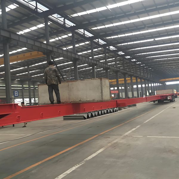
Telescopic Deck Reference
This BOCA extendable flatbed trailer provides a visual reference for a telescopic deck mechanism. It should not be used to infer the support positions of every lowboy or lowbed design. Final bearing zones and concentrated-load limits must be confirmed for the specific trailer and extension setting.
View the Extendable Flatbed TrailerStart with the Cargo, Not the Empty Deck
Overall cargo length is usually the first measurement available, but it does not show where the weight sits or which parts of the underside can safely accept concentrated bearing.
A long industrial machine can look visually balanced while a gearbox, drive unit, hydraulic assembly, counterweight, or reinforced housing places much more mass near one end. The geometric center should not automatically be treated as the center of gravity.
Fabricated structures can be equally deceptive. Plate thickness may change along the frame, and welded nodes, stiffeners, crossmembers, openings, or local reinforcement can make one section much stronger than the next.
What actually changes the support decision?
Suppose a fabricated skid has two reinforced end frames, a lighter middle section, and a heavy drive unit close to the rear. Its overall length suggests a simple two-point layout near the quarter points. The cargo structure suggests something different: each support needs to sit beneath an approved reinforced zone, while the rear position must also account for the concentrated mass of the drive unit.
Before positioning dunnage, confirm the verified transport weight, known center of gravity, heavy components, transport orientation, approved lifting or support zones, and any areas where concentrated bearing is prohibited. Cargo drawings and transport instructions are more reliable than judging the underside by appearance.
The underside deserves its own inspection. A broad flat panel may conceal the real base rail above it. A block placed under the easiest visible surface can begin crushing a cover, tank guard, enclosure, or thin plate before a meaningful reaction reaches the cargo frame.
Weight information helps identify where larger reactions may occur. Stiffness information shows whether the cargo can span between those reactions. Both affect support spacing.
If permitted bearing zones cannot be confirmed from drawings, markings, transport instructions, or qualified technical guidance, loading should pause. Do not copy the support positions of a visually similar load and assume the structural arrangement is the same.
Choose Supports Around Strong Cargo Zones
Once the cargo structure is understood, the first layout should follow its strongest permitted bearing areas. On machinery, these may align with base rails or a transport frame. On fabricated members, the intended path may run through stiffeners, webs, diaphragms, saddles, or reinforced nodes.
The key is structural continuity. A support should transfer reaction into a part capable of carrying that force through the cargo. A convenient flat surface proves only that physical contact is possible.
This changes the usual loading sequence. Instead of choosing two easy positions on the trailer and forcing the cargo to match them, use the approved cargo bearing zones to create the first version of the support geometry.
Test every proposed support with four questions
1. Can the cargo structure at this position accept a concentrated vertical reaction?
2. Does the known weight distribution create an unusually high reaction near this point?
3. What trailer structure sits directly below the support after the deck is extended?
4. Can the dunnage connect both structures with a stable footprint and practical height?
Support spacing also changes the way the cargo spans. Moving two supports farther apart may reduce the free length at the front and rear, but the span between the supports becomes longer. Moving them inward shortens the supported span while increasing the end overhang.
Neither wide nor narrow spacing is automatically safer. A flexible beam, a rigid machine base, and a fabricated frame with several structural sections can require different layouts even when their overall lengths are similar.
For flexible, irregular, or high-value loads, the correct spacing may depend on manufacturer transport instructions, structural calculations, or qualified engineering review. The trailer deck should not be used to compensate for an unconfirmed cargo bearing arrangement.
Dunnage becomes part of the load path
Once the cargo lands, the dunnage is the connection between the cargo and trailer. Its footprint, orientation, height, material condition, and contact surface all affect how the reaction is transferred.
A narrow block can increase local bearing pressure. An unnecessarily tall support pack may be easier to shift or overturn. If different materials or damaged blocks are mixed in one layout, they may compress differently as the crane releases the weight.
No single timber size, block height, or contact area is suitable for every load. When reactions are high or the permitted bearing zones are limited, the dunnage arrangement needs technical confirmation rather than a visual estimate.
Control Overhang Without Creating a Worse Support Point
Overhang is the cargo length extending beyond its nearest support, but visible length is only part of the condition. The amount and position of weight inside that free section matter just as much.
A light steel extension and the end of a machine containing a drive assembly may project the same distance. The machine end can create a much larger bending effect around the support.
Why “move the block outward” is not always the answer
Moving a support toward the end of the cargo can reduce visible overhang. If that new position lands beneath a thin enclosure or over an unsuitable section of the extended trailer, the shorter overhang has been achieved by creating a weaker load path.
Read overhang in three ways. Structurally, ask whether the unsupported section can carry its transport loads beyond the nearest support. Operationally, check whether the projection interferes with articulation, restraint access, lighting, loading equipment, or unloading work. Legally, confirm that the final projection meets the permit, marking, route, and destination-country requirements.
A weak-looking end section does not always need an improvised block. If it is designed to cantilever from a stronger frame, placing support beneath a thin panel may cause local damage. The opposite condition is also possible: a reinforced end frame may need direct bearing close to the cargo end.
Minimum deck extension is therefore not always the correct target. The working length should allow the approved cargo bearing zones to align with suitable trailer structure. At the same time, unnecessary extension should be avoided because it increases the complete vehicle envelope and can make site turns more difficult.
Match Each Support to the Trailer Below
Strong cargo zones solve only half the problem. Each reaction must also enter an appropriate part of the trailer. The structure below the deck deserves the same attention as the cargo above it.
An extended platform can contain fixed frame members, sliding members, crossmembers, transition areas, locking positions, and extension interfaces. These arrangements vary by design, so the visible deck surface should not be treated as a map of equal structural capacity.
The telescopic transition deserves particular caution. The joint is designed to transfer structural forces, but the permitted concentrated-load positions depend on the specific trailer. A large reaction should not be placed close to an unverified transition merely because the upper surface appears flat.
Where the trailer drawing or loading instructions identify intended bearing regions, those references should control the layout. If the information is unavailable and a support is expected to carry a significant reaction, confirm the position before loading.
Moving the cargo also changes vehicle loading
A support position can be suitable for the cargo and trailer structure while the overall cargo position still creates an unsuitable vehicle load distribution. Moving the cargo forward or rearward changes the reactions carried toward the tractor connection and the trailer axle group.
There is no universal front-to-rear distribution that can be applied to every extendable trailer. Tractor geometry, trailer configuration, suspension arrangement, cargo center of gravity, route conditions, and destination regulations all influence the result.
Do not move a support away from an approved cargo bearing zone simply to improve an estimated axle reaction. Reconsider the complete cargo position, working extension, or trailer configuration instead.
A workable support connects three compatible layers
Cargo above: a confirmed structure that can receive the reaction.
Dunnage between: a stable arrangement that can transfer it.
Trailer below: a suitable structural path in the actual extended condition.
Watch What Happens When the Crane Releases the Load
The support plan is not finished when every block first touches the cargo. Once lifting tension is released, the deck, dunnage, and cargo settle into their actual loaded geometry.
Some elastic movement can occur in structural systems. What matters is whether the loaded condition matches the intended layout. Unexplained local deformation, progressive sagging, cracked cribbing, a widening gap, or a support that suddenly becomes loose needs attention.
A loose support may indicate uneven block height, trailer deflection, cargo bending, or an incorrect assumption about how the reactions would be shared. One block compressing much more than the others may be carrying more load than expected.
Adding a wedge simply to remove a visible gap can change the reaction distribution again. Understand why the gap appeared before changing the support height.
Pause before dispatch if the loaded condition changes unexpectedly
A block that loses contact, increasing local deformation, crushed dunnage, or visibly unequal compression should be investigated. Restraints should not be used to pull a flexible cargo section down onto a support that was not carrying weight naturally.
Leave Room for Restraints, Turning and Unloading
A structurally suitable block can still create an operational problem if it covers the only practical restraint point. Long machinery may have only a few approved tie-down locations, while fabricated cargo may require chain access around specific frame members.
Check chain paths, strap clearance, edge protection, and access around the support packs before final loading. The restraints should secure an already stable load rather than force the cargo onto poorly positioned supports.
The unloading method matters at the same stage. Crane lifting points, hydraulic jacks, forklifts, skidding equipment, or receiving stands may need access beneath the cargo. A transport support placed directly in that working area can create a new problem at the destination.
Check the complete extended vehicle envelope
A longer combination can look comfortable in a straight loading lane and still run out of room at the first tight turn. The front of the cargo can approach the tractor during articulation, while the rear end sweeps farther outward.
Industrial sites often reveal this problem before the public road does. A fabrication yard may have a narrow exit followed by stored steel on one side. A construction site may combine a tight gate, temporary barriers, uneven ground, and consecutive turns.
The route review should include the origin and destination yards, not only highway travel. Measure the full cargo envelope, including attachments that project beyond the main frame.
Vertical and underside clearance also need attention. Long machinery may have pipes, brackets, tanks, or guards below its main base rails. Ramps, crowns, drainage channels, and surface transitions can reduce ground clearance as the extended trailer crosses them.
If unstable dunnage, abnormal deformation, inadequate restraint access, unresolved axle loading, or insufficient turning clearance remains after the load settles, dispatch should stop. Applicable regulations, cargo instructions, site procedures, and qualified technical guidance should control the next decision.
Record the Layout So It Can Be Checked Again
Once the arrangement works, make the geometry measurable. Descriptions such as “nearly fully extended” or “the rear block is close to the axle area” are difficult to verify during later inspections.
Use fixed reference points. Record the actual deck extension, cargo position, support spacing, and front and rear overhang. Simple support labels such as S1, S2, S3, and S4 make it easier to connect the cargo feature above each point with the trailer region beneath it.
For each support, note its measured position, dunnage material and arrangement, the cargo structure above it, and the trailer structure below it. Also record restraint positions, critical articulation or rear-sweep clearances, and any areas that need to remain open for unloading.
Photographs should show more than the complete trailer. Close views of each support are useful when checking contact, compression, or movement, while side views document overhang and cargo position.
This record becomes particularly valuable after the first controlled movement. A shifted block, new gap, or change in restraint tension can be compared with the starting condition instead of being judged from memory.
Repeated transport of the same engineered load may eventually use a controlled standard layout. That layout should remain tied to the same cargo configuration and trailer setup. Attachments, weight distribution, transport orientation, extension position, or route conditions can change the decision.
Frequently Asked Questions
Where should a long load be supported on an extended lowboy?
Begin with cargo zones confirmed to accept concentrated bearing. Then check whether those positions align with suitable structural regions of the trailer in its actual extended condition.
Equal spacing along the deck is not enough. Cargo stiffness, center of gravity, dunnage stability, trailer structure, overhang, and vehicle load distribution all affect the final arrangement.
How does overhang affect the support layout?
Overhang creates a free cargo section outside the nearest support. As that section becomes longer or carries more weight, the bending effect around the support can increase.
Moving a support outward may reduce overhang, but only when the new position remains suitable for both the cargo structure and the trailer beneath it.
Why should cargo strength be checked before positioning dunnage?
Dunnage transfers a concentrated reaction into the cargo. A flat underside may belong to a cover, enclosure, shell, tank, or thin panel that was not designed as a transport bearing zone.
Use drawings, transport instructions, marked support zones, reinforced base rails, or qualified technical guidance when the cargo structure is uncertain.
Do more support points always reduce deflection?
No. Additional supports only help when the cargo and trailer can share reactions across them predictably.
Unequal support height, cargo flexibility, deck deflection, or different dunnage compression can leave one point lightly loaded while another carries a much higher reaction. The required number and position of supports must be confirmed for the specific cargo and trailer configuration.
Set the Support Geometry Before Finalizing the Extension
Long-load planning works best when the cargo structure leads the decision. Identify approved bearing zones and concentrated weight first. Then establish workable support spacing, dunnage position, and free-end length.
Match those positions with the trailer structure in its real extended condition. Before dispatch, check vehicle load distribution, restraint access, articulation, rear sweep, ground clearance, route conditions, and the unloading sequence.
- Confirm cargo weight distribution and permitted bearing zones before accepting the final extension.
- Measure every support position, overhang, and critical clearance after the cargo settles.
- Stop for technical review when cargo strength, trailer structure, axle loading, deflection, or dunnage stability remains uncertain.
Long-Load Configuration Review
Match the Trailer Configuration to the Actual Cargo
When comparing a trailer for long-load transport, prepare the cargo length, verified transport weight, known weight distribution, approved bearing areas, required deck extension, loading and unloading method, destination country, route conditions, and underside drawings or photographs.
These details allow the platform length, frame arrangement, axle configuration, and support geometry to be considered around the real transport condition rather than cargo length alone. Where the cargo’s structural limits remain uncertain, qualified engineering review should remain separate from trailer selection.