

Gooseneck Shipping Container Trailer: How to Verify Tractor Coupling Height Before High-Cube Container Pickup

A tractor can back cleanly under a chassis, lock the kingpin, and still leave the loaded combination sitting at the wrong working attitude. Before a high-cube pickup, a practical gooseneck container trailer coupling height check needs more than one fifth-wheel number. Tractor ride height, chassis geometry, kingpin engagement, front-frame clearance, loaded suspension position, and the planned route all need to make sense together.
The problem often appears late in an otherwise routine pickup. An empty skeletal chassis looks familiar in the terminal lane, and the tractor couples without an obvious struggle. Then the high-cube container lands, the suspension settles, and the front of the chassis appears higher than expected.
At that point, the issue is no longer whether the trailer can physically connect. The useful question is whether the tractor and chassis form a sensible operating combination. A poor vertical match can change chassis attitude, tighten clearance around the tractor, and increase the loaded height presented to bridges, canopies, tunnels, terminal structures, or other route restrictions.
A reliable check follows the combination through three conditions: the tractor before coupling, the chassis after the kingpin is fully engaged, and the complete vehicle after the high-cube container has transferred its weight to the chassis. Each stage answers a different question, and none should be replaced by a single remembered fifth-wheel dimension.
A clean fifth-wheel lock is only the first check
A successful lock proves that a mechanical connection has been made. It does not, by itself, prove correct chassis ride attitude, adequate articulation clearance, suitable hose routing, or acceptable loaded transport height.
Why Gooseneck Container Trailer Coupling Height Matters
Once coupled, the tractor and chassis act as one geometric system. The fifth wheel establishes the front support position, while the chassis tires and suspension establish the rear support position. Raising or lowering the tractor interface can therefore change the attitude of the complete chassis rather than simply altering one isolated dimension.
This is especially important with a gooseneck shipping container trailer. The shaped front frame is designed to work within a particular tractor-chassis relationship. A fifth-wheel setup that works well with another semi-trailer should not automatically be treated as correct for a different skeletal chassis.
If the chassis itself is still being selected, BOCA’s container chassis range can be used to compare 20 ft, 40 ft, 45 ft, axle, suspension, and frame configurations before the tractor interface is finalized.
High-cube work leaves less room for a poor vertical match. The container already occupies more vertical space than a standard-height unit. If the tractor raises the chassis front beyond the intended operating position, the loaded roof can also sit unnecessarily high relative to the road.
The problem may not be obvious while the chassis is empty
An empty chassis can tolerate visual differences that become much clearer once the container lands. The tractor suspension, chassis suspension, tires, and frame settle under working load. A combination that looked nearly level during coupling may then develop a noticeable nose-high attitude.
The opposite condition deserves the same attention. If the chassis nose sits unusually low, clearance between the gooseneck structure and tractor frame, mudguards, catwalk equipment, hoses, or other components can tighten.
Neither a higher nor a lower fifth wheel is automatically better. The correct result is the one that agrees with the selected chassis geometry and remains workable after loading, steering, and vertical articulation.
Identify the Tractor and Chassis Reference Points
Useful measurement starts by deciding exactly what is being measured. Two readings from the same tractor can disagree simply because one person measured the rear approach ramp of the fifth wheel while another measured the actual surface that supports the trailer upper coupler.
Measure the fifth-wheel working surface
For the tractor, the key vertical reference is normally the distance from firm, level ground to the fifth-wheel surface that carries the trailer upper coupler after full engagement. That distinction matters because a fifth wheel contains approach ramps, contours, grease channels, and the kingpin throat.
A reading taken only at the rear ramp can misrepresent the true support height. Where the tractor or fifth-wheel manufacturer defines a measurement point, that reference should control the reading.
The tractor must also represent its normal road configuration. For an air-suspended unit, put the suspension at its specified transport ride position. Record tire size, fitted wheel configuration, fifth-wheel mounting, and the slide position if the fifth wheel is adjustable.
Do not confuse landing-gear height with chassis design height
An uncoupled chassis can be raised or lowered substantially with the landing gear. Ground-to-front-frame height while parked mainly describes the temporary setup used to make coupling possible. It does not establish the chassis’s intended road attitude.
The stronger reference is the drawing for the exact chassis configuration. It can identify the intended fifth-wheel interface, gooseneck profile, axle group, suspension arrangement, tire specification, kingpin position, and dimensions that affect the tractor connection.
If the relevant reference is unclear on the drawing, obtain technical confirmation instead of estimating from a photograph or copying a dimension from another chassis that merely looks similar.
Chassis Geometry Reference
Locate the gooseneck, landing gear, and tractor interface before measuring
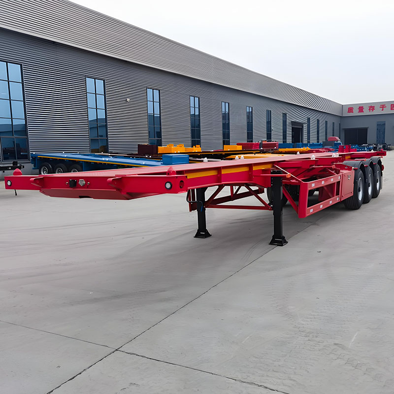
The BOCA 40 ft chassis below provides a clear view of the front skeletal frame, gooseneck profile, landing gear, and tractor coupling area. Use the physical layout to understand where clearance needs to be checked, but use the technical drawing—not the photograph—to approve dimensions.

How to Measure the Fifth-Wheel and Coupling Height
Once the reference points are clear, the physical measurement should remain simple and repeatable. Park the tractor on firm, level ground, allow the suspension to settle into its normal transport position, and measure vertically from the ground to the defined fifth-wheel working surface.
A rigid measuring staff or another suitable height tool can make the reading easier to reproduce. The yard surface matters just as much as the tool: a drainage slope, wheel rut, soft shoulder, or uneven pavement can create a false difference across the tractor.
Do not average away an unexplained difference
If the fifth-wheel position appears different from one side to the other, investigate why. Ground slope, tire condition, suspension behavior, or fifth-wheel mounting may explain the result. Simply averaging the readings can hide the condition that actually needs attention.
Compare the confirmed tractor measurement with the drawing for the selected chassis. There is no useful universal height difference that automatically proves compatibility across every tractor and chassis combination. The relevant question is whether this tractor can support this chassis in its intended operating attitude.
Watch the approach before the kingpin locks
The coupling approach provides information before any tape measure is used again. As the tractor reverses beneath the chassis, the fifth wheel should guide under the upper coupler without striking the kingpin, slipping beneath the plate incorrectly, or lifting the chassis in an obviously abnormal way.
Landing gear can be adjusted under the applicable coupling procedure. Repeatedly making large landing-gear corrections, however, should not become the routine method used to make every tractor appear compatible with the same chassis.
Extra reversing force is not a substitute for correct geometry. If the kingpin and fifth wheel do not meet naturally after a controlled reset, stop and review the height relationship instead of forcing the connection.
Recheck after the tractor supports the chassis
After full coupling and landing-gear retraction, the fifth wheel supports the front of the chassis. The temporary uncoupled landing-gear position no longer matters. The chassis attitude should now be compared with the intended geometry in its coupled state.
Air suspension requires particular discipline because yard, coupling, and normal road settings can differ. A reading taken while the tractor remains raised, lowered, or dumped can give the wrong impression of the actual transport condition.
Mechanical suspension should also be measured rather than assumed. Tire wear, spring condition, repairs, loading, and replacement components can change the real operating height even when there is no adjustable air system.
Check Kingpin Engagement and Gooseneck Clearance
A sensible coupling-height relationship still needs a correct mechanical connection. Before coupling, inspect visible kingpin and upper-coupler areas for deformation, unusual wear, damaged mounting, contamination, or another condition that could interfere with normal engagement.
The fifth wheel should also meet the tractor manufacturer’s, fifth-wheel manufacturer’s, and fleet inspection requirements. Locking components, the plate surface, release mechanism, mounting, and lubrication all affect coupling. A generic handle position or remembered pull-test procedure should not replace the equipment-specific instructions.
Confirm plate contact as well as the lock
After engagement, the trailer upper coupler should sit correctly against the fifth-wheel supporting surface. A visible gap can indicate incorrect pickup height, incomplete coupling, contamination, deformation, or another condition that needs investigation.
A release handle that appears to be in its normal position does not prove complete engagement. The locking condition around the kingpin should be positively verified from a safe position under the applicable fleet procedure.
Straight-ahead clearance is only the starting point
With the tractor and chassis aligned, inspect the gooseneck relative to the tractor frame rails, mudguards, catwalk components, fifth-wheel structure, hoses, electrical connections, and nearby accessories. Clearance should be mechanically understandable rather than merely “close but probably acceptable.”
Steering changes that relationship. As the tractor turns, the chassis front sweeps across a wider part of the tractor. At the same time, a ramp, weighbridge approach, drainage dip, yard depression, or crest can change vertical articulation between the two units.
Clearance observed while the vehicle is straight on flat concrete does not automatically prove clearance during the first terminal turn or ramp transition.
Include air and electrical lines in the same check
Steel-to-steel clearance can look acceptable while an air line becomes tight during steering. Too much slack creates the opposite problem by allowing a hose or electrical connection to enter a rubbing, trapping, or pinch zone.
Connections should follow the approved tractor and chassis routing. Stretching, rubbing, trapping, or contact near hot or moving components should be corrected before dispatch.
Extended Gooseneck Reference
Longer chassis still require tractor-specific front-frame clearance
The 45 ft chassis below shows another real BOCA gooseneck/front-frame arrangement. It is useful when reviewing how an extended chassis approaches the tractor, but chassis length alone does not determine whether a high-cube pickup is suitable. Container size, tractor interface, turning envelope, axle requirements, and the intended route still need to be checked together.
Evaluate the Loaded Ride Height Before Dispatch
The empty coupling check answers whether the tractor and chassis connect in a sensible way. The road, however, will see the loaded combination. The final height assessment belongs after the high-cube container is seated and both tractor and chassis suspensions have reached their normal transport positions.
A temporarily raised tractor can produce a misleading overall-height reading. A chassis that has not settled after loading can also sit differently from its stable operating condition.
Measure the actual combination instead of adding catalogue numbers
The useful field measurement is the highest applicable point of the loaded combination above the operating surface. Take the measurement in a safe, suitable location rather than estimating the result by adding a nominal container height to a catalogue chassis dimension.
High-cube container height is only one part of the result. Fifth-wheel elevation, chassis geometry, suspension state, tires, loading, and the surface beneath the vehicle all influence the final transport height.
A measurement from one tractor should not automatically be copied to another tractor assigned later. Even similar tractor units can differ in tire configuration, fifth-wheel mounting, suspension setup, or normal ride position.
Do not rely on one universal road-height number
Road-height rules vary between countries, regions, road networks, and permit systems. A combination can satisfy a general legal limit and still encounter a lower bridge, terminal canopy, warehouse entrance, tunnel, ferry interface, utility structure, or temporary restriction.
Compare the measured vehicle with current route information and applicable regulations. Permit requirements, axle loads, infrastructure restrictions, and engineering decisions should remain subject to current local rules and qualified technical review where required.
A familiar route can still change
Repeated work on the same corridor can create false confidence. Road resurfacing, construction, lane changes, utility repairs, temporary gantries, or modified terminal circulation can alter the usable envelope.
Previous successful movements are valuable operating history, but they are not permanent clearance certificates for every later tractor, chassis, and container combination.
How to Interpret the Result: Proceed, Recheck, or Stop
The purpose of the measurement is not to produce a number for the file. It should lead to a practical decision. The following signs help separate a normal pickup from a combination that needs remeasurement or technical review.
| What you observe | What it may indicate | Best next action |
|---|---|---|
| Kingpin approaches naturally, full plate contact is confirmed, and chassis attitude matches the drawing. | The basic tractor-to-chassis interface appears sensible. | Continue to loaded-height, articulation, securing, and route checks. |
| Kingpin strikes, chassis lifts abnormally, or repeated landing-gear adjustment is needed. | Pickup height or approach geometry may be wrong. | Reset, remeasure the tractor and chassis references, and do not force the coupling. |
| Chassis becomes noticeably nose-high after the high-cube container lands. | The loaded tractor-chassis relationship may be raising the front more than expected. | Confirm suspension state, fifth-wheel measurement, chassis drawing, and loaded overall height before dispatch. |
| Front-frame clearance becomes tight while turning or crossing a dip or crest. | Static straight-ahead clearance is insufficient for the real articulation envelope. | Stop and review the tractor/chassis geometry or intended operating path. |
| Loaded height is acceptable in the yard but route clearance is uncertain. | The vehicle measurement is known, but dispatch suitability is not. | Verify the actual route, restrictions, and applicable requirements before movement. |
Use a Three-Stage Pickup Check
A repeatable field process makes the earlier measurements useful. The aim is to catch a mismatch while reassignment, remeasurement, or adjustment is still practical—not after the loaded vehicle reaches the terminal exit.
Stage 1: Before coupling
- Confirm the tractor suspension is at its normal operating ride height.
- Confirm the fitted tire and wheel configuration.
- Record the fifth-wheel mounting and slide position where applicable.
- Match the chassis identification with the drawing being reviewed.
- Inspect the kingpin and visible coupling area before engagement.
The record should describe the tractor physically present at the site. If another tractor has replaced the scheduled unit, confirm its own configuration rather than inheriting measurements from the previous assignment.
Stage 2: After coupling
- Confirm complete upper-coupler contact with the fifth-wheel supporting surface.
- Positively verify the kingpin locking condition under the applicable procedure.
- Retract the landing gear and allow the chassis to settle on the tractor.
- Check whether the empty chassis attitude agrees with the expected geometry.
- Review front-frame, hose, and electrical-line clearance before movement.
A short controlled move can help reveal whether the combination settles and articulates normally, but it does not replace the formal coupling inspection.
Stage 3: After the high-cube container lands
Container handling should remain under terminal procedures and lifting-equipment exclusion rules. Once the box is seated and the lifting equipment has cleared under the approved process, move the combination to a designated inspection position.
- Confirm tractor and chassis suspensions are at normal transport positions.
- Check container seating and securing condition.
- Review loaded chassis attitude from the side.
- Recheck gooseneck and tractor-component clearance.
- Check hoses and electrical lines for stretch, rubbing, or pinch points.
- Confirm landing gear is fully retracted as required.
- Measure loaded overall height before route clearance is accepted.
Where the site permits a controlled steering check, observe how the chassis front moves relative to the tractor. Use safe observation positions; no person should enter a pinch zone for a closer view.
If the terminal exit includes a weighbridge approach, steep ramp, drainage dip, or crest, the articulation question should be resolved before the loaded combination reaches it.
When should the pickup stop for technical review?
You do not need a complete engineering diagnosis before deciding not to dispatch. The operation only needs enough evidence to show that the intended coupling, clearance, suspension, or route condition cannot yet be confirmed.
- The kingpin repeatedly approaches the fifth wheel at an abnormal angle.
- Full fifth-wheel and upper-coupler contact cannot be confirmed.
- The chassis repeatedly needs unusual landing-gear adjustment to meet the tractor.
- The front frame, hoses, or connections approach tractor components too closely.
- Loaded chassis attitude differs substantially from the expected drawing or previous verified configuration.
- Normal suspension ride height cannot be confirmed.
- Loaded transport height has not been cleared for the actual terminal and road route.
What Measurements to Send Before Ordering or Dispatch
A technical review becomes much more useful when it starts with actual vehicle information. Statements such as “the tractor seems high” or “the chassis sits low” do not show whether the difference comes from fifth-wheel mounting, suspension position, tires, the chassis specification, or the measurement method.
Instead, build one record that connects the tractor, chassis, container, and intended route. The same record also makes later tractor substitutions easier to evaluate.
Tractor information
- Tractor make, model, and axle configuration.
- Measured ground-to-fifth-wheel working-surface height.
- Exact fifth-wheel measurement reference point.
- Fifth-wheel model and mounting arrangement when available.
- Slide position when an adjustable fifth wheel is fitted.
- Tire size and current fitted configuration.
- Suspension type and normal transport ride setting.
- Recent changes to tires, suspension, frame, or fifth-wheel mounting.
Chassis and container information
- Exact chassis model or technical drawing reference.
- Front-frame or gooseneck profile drawing.
- Intended fifth-wheel or upper-coupler reference dimension.
- Chassis suspension and tire configuration.
- Kingpin and coupling-area information from the applicable drawing.
- Container size and type planned for the route.
- High-cube identification where applicable.
- Verified container or cargo mass information where available.
Route and site information
- Origin terminal, depot, or loading site.
- Planned road route.
- Known bridges, tunnels, canopies, warehouse entrances, or industrial structures.
- Steep ramps, yard depressions, weighbridge approaches, or crests.
- Applicable permits or route restrictions.
- Current photographs of the tractor fifth-wheel installation and chassis front area.
If the chassis configuration itself is not yet finalized, BOCA’s container chassis specifications and configuration guide can help separate coupling-height questions from axle, suspension, chassis type, and wider purchasing decisions.
For recurring work, keep the confirmed configuration as operating history, but review it whenever the equipment changes. New tires, suspension repairs, fifth-wheel replacement, a different mounting arrangement, or another chassis specification can make an old height record unreliable.
Product matching should also remain separate from legal approval. Axle loading, road-height limits, permits, bridge restrictions, and other regulatory matters must follow current destination-country rules and qualified technical guidance where required.
FAQ
The final decision comes from the complete operating configuration
A high-cube pickup should not depend on one remembered fifth-wheel number. Tractor measurement, chassis drawing, kingpin engagement, suspension condition, loaded attitude, articulation clearance, and route height should all describe the same workable combination.
Before the next pickup, focus on three actions:
- Measure the tractor correctly: confirm fifth-wheel working height on level ground and record tires, suspension, mounting, and slide configuration.
- Match the exact chassis: compare the tractor record with the correct chassis drawing, then recheck gooseneck clearance and chassis attitude after loading.
- Clear the real route: measure the loaded combination and verify the terminal and road route rather than relying on a generic height assumption.
High-Cube Chassis Matching Review
Send the Tractor, Chassis, Container, and Route Details Before Final Matching
For a useful review, send the measured fifth-wheel working height, tractor tire and suspension configuration, fifth-wheel mounting details, intended container type, available load information, chassis drawing or model, and any known route-clearance restrictions.
Those details allow the gooseneck container trailer coupling height discussion to focus on the real tractor-chassis interface rather than a generic fitment assumption. If the chassis has not been selected yet, compare the available container chassis configurations first and then submit the tractor data for matching.