

Two Machines on One Lowboy Trailer: Weight & Axle Limits

A second machine can look like an easy way to avoid another haul. The deck appears long enough, and the two listed weights may still look manageable. However, two machines on one lowboy trailer become one load system as soon as both units reach the deck. Combined mass, machine position, kingpin reaction, axle-group loading, securement access, and unloading order must all work together before the move makes sense.
The situation often develops late in a project. An excavator has finished one phase of work, while a roller, compact loader, paver, or smaller tracked unit also needs to leave the site. Meanwhile, one trailer is already scheduled for the move.
From the ground, the decision can look simple. The first machine occupies most of the low deck, yet several meters of platform remain visible. The smaller unit appears to fit neatly into that empty area.
That visual impression can be misleading. Empty deck length is not automatically unused carrying capacity. Instead, the second machine changes how weight travels through the deck, kingpin, trailer running gear, fifth wheel, and tractor axles.
For that reason, a two-machine load should be judged as one complete configuration. The useful question is not simply whether both footprints fit. It is whether both machines can occupy workable positions while structural, axle, securement, dimensional, and legal conditions remain acceptable at the same time.
The quickest way to frame the decision
Do not stop at “the combined weight is below trailer capacity.” A workable combination also needs acceptable machine positions, kingpin reaction, tractor and trailer axle loading, securement access, machine clearance, and a practical loading sequence.
Why Two Smaller Machines Are Not Automatically One Acceptable Load
Combined machine weight is a useful first screening number. However, it says nothing about where that mass acts. One compact machine may place most of its load over a short track area, while a longer machine may carry substantial mass toward one end of its visible footprint.
As a result, the trailer can remain below an overall payload figure while one support region becomes too heavily loaded. The limiting condition may appear at the kingpin, trailer running gear, tractor axle group, tires, coupling, or a concentrated deck area instead of at total cargo mass.
Deck space and load-distribution space are different
An empty section of deck often looks inviting after the first machine is parked. Nevertheless, that remaining space may sit on the wrong side of the workable balance window. Filling it can shift too much reaction toward the trailer axles or too much load toward the tractor.
Likewise, moving the first machine to create room for the second can solve one problem while creating another. An anchor point may disappear beneath a track. A counterweight may approach the gooseneck. Alternatively, the rear machine may lose enough room for controlled unloading.
The second machine changes the first machine’s acceptable position
With a single machine, the deck may offer useful freedom to adjust longitudinal position. Once another footprint arrives, that freedom can shrink quickly. Therefore, Machine A should not be considered permanently positioned before Machine B is included.
Instead, both units should appear on one lowboy load plan. Detached attachments, work tools, blocking, securement zones, deck contact areas, and required separation belong on the same layout.
Verify Each Machine’s Actual Transport Weight
A combined calculation cannot become more reliable than the information entered into it. Therefore, each machine needs a transport weight that matches the configuration actually arriving at the trailer.
A published machine weight may describe a standard setup. On site, however, the same model can carry a different bucket, breaker, blade, quick coupler, counterweight package, guarding system, or auxiliary equipment. Those differences become important when the load plan has limited margin.
The problem is particularly easy to miss at the end of a job. A breaker remains installed because the machine will work again at the next location. A larger bucket has replaced the standard attachment. Meanwhile, loose tooling is placed on the trailer rather than sent in another vehicle.
Record what the weight figure actually includes
A useful transport record connects each number with the real machine condition. Manufacturer documentation can provide a starting point. Meanwhile, a suitable weighing method may provide stronger evidence where configuration details remain uncertain.
Machine identity
Record the exact model, operating configuration, attachment package, counterweight arrangement, and any meaningful modification that changes transport mass.
Transport condition
Include installed work tools, detached attachments carried on the same trailer, fuel condition, loose equipment, blocking, and other significant cargo.
Weight evidence
Keep the source and date of each figure visible. Where documentation cannot support a critical assumption, suitable weighing or qualified technical review should close the gap.
Detached attachments still belong in the load
Removing a bucket, blade, or work tool can reduce the machine footprint or change its center of gravity. However, the attachment does not disappear if it remains on the same trailer. Instead, it becomes another load item with its own mass and position.
That position matters. A detached tool stored close to the trailer running gear affects the support reactions differently from the same mass located farther forward. Therefore, attachment location should be recorded rather than hidden inside one combined cargo figure.
Do not hide uncertainty inside a precise-looking total
One machine may have a verified transport weight while another only has an approximate operating figure. Adding the two values produces a clean total, but it does not remove uncertainty.
If the missing information could change structural loading, axle compliance, permit status, or the basic go/no-go decision, the plan should remain provisional until better evidence is available.
Map Both Centers of Gravity and Footprint Lengths
Weight establishes how much load enters the trailer. Geometry determines where that load acts. Consequently, each machine needs two separate references: the physical space it occupies and the approximate longitudinal location of its center of gravity.
The distinction is easy to miss on tracked equipment. A machine can appear nearly symmetrical from above while a rear counterweight, boom position, engine package, or attachment moves the actual balance point away from the geometric center.
Use contact length and overall length for different questions
Overall transport length shows whether the machine physically fits. Track or tire contact locations help describe how the machine loads the deck. Meanwhile, the center-of-gravity reference supports the front-rear reaction calculation.
For example, a bucket can project beyond the front of a tracked machine. That projection consumes physical space, but the bucket tip is not where the entire machine mass acts. Treating projection length and load-center position as the same measurement can distort equipment placement decisions.
A useful deck sketch should show
- Usable deck start and end points
- Kingpin and trailer axle-group references
- Machine A footprint and longitudinal load center
- Machine B footprint and longitudinal load center
- Attachment projections and separate cargo
- Machine-to-machine clearance
- Anchor locations and securement working areas
Once those references appear on one drawing, hidden conflicts become easier to see. The two footprints may fit while leaving almost no useful balance adjustment range. Alternatively, a small change in orientation may create enough room to test another practical arrangement.
Machine order also becomes clearer on the sketch. A compact roller can sometimes use a short section of deck, while a longer excavator consumes more longitudinal space. However, the smaller machine may still sit in a position that creates an undesirable axle reaction.
Orientation changes should still follow machine transport instructions and safe operating practice. A mathematically useful position is not acceptable if the equipment cannot travel in that configuration.
Test Front-Rear Placement Against Kingpin and Axle Groups
This is the stage where two-machine planning becomes more than a deck-fitting exercise. Moving either machine changes the reaction carried through the forward coupling region and the trailer running gear. Therefore, several realistic arrangements should be tested before one position becomes preferred.
As a general load-transfer principle, moving mass rearward tends to increase rear support reaction. Moving the same mass forward tends to transfer more reaction toward the coupling. However, the real values depend on trailer geometry, tractor geometry, tare distribution, axle spacing, and the actual load centers.
Putting the heavier machine forward can solve one problem and create another
A forward heavy machine may reduce trailer axle-group reaction. Nevertheless, increased kingpin reaction still enters the tractor through the fifth wheel. The tractor drive or steer axle condition can then become the next restriction.
Physical geometry can interfere as well. A large rear counterweight may approach the gooseneck, while a boom or attachment consumes the exact deck area needed to move the second machine into a better position.
Putting the heavier machine rearward changes the problem
Moving heavy mass rearward may reduce forward reaction. However, the trailer running gear can receive more load. Rear clearance, ramps, overhang, attachment projection, and unloading sequence can also become more restrictive.
Therefore, “heaviest forward” and “heaviest rearward” are both poor universal rules. The better position is the one that satisfies the complete tractor-trailer combination rather than one isolated number.
Axle-Group Planning
Multi-Axle Geometry Makes Load Position More Important, Not Less
A multi-axle lowboy provides another configuration for heavy-equipment transport. However, additional axles do not make equipment placement irrelevant. The final layout still has to work with trailer ratings, tractor reactions, axle spacing, local axle-group rules, and route conditions.

The visible multi-axle running gear makes this configuration relevant to axle-group planning. Final allowable loading still depends on the actual machine arrangement, trailer ratings, tractor configuration, and destination rules.
The tractor must stay inside the same calculation
Kingpin reaction is not simply a trailer number. Instead, that reaction enters the tractor through the fifth wheel and redistributes across the tractor wheelbase. Fifth-wheel position and tractor tare axle weights therefore affect the final axle-group picture.
Similarly, total trailer axle reaction may not be the only legal concern. Applicable rules can address individual axles, grouped axles, axle spacing, tire ratings, gross combination mass, bridge loading, or permit-specific limits.
Run several realistic placement scenarios
A useful load plan usually tests more than one arrangement. The heavier machine can be moved forward, then rearward. One machine may be reversed when its approved transport configuration allows it. Meanwhile, the gap between the two units can be adjusted within the securement and clearance requirements.
Those variations reveal whether the load has a usable operating window. If only one exact theoretical position produces acceptable reactions, the combination deserves additional scrutiny. Real machinery rarely parks on a mathematical point with zero variation.
For this reason, simplified reaction calculations are best used as planning tools. Manufacturer data, approved weighing, applicable regulations, permit requirements, and qualified engineering review remain controlling where required.
Check Securement Access, Clearance and Loading Order
A balanced arrangement can still fail on the deck. For example, the rear machine may cover an anchor point needed for the forward machine. Alternatively, the gap between the units may become too narrow for a chain, binder, chock, blocking point, or inspection route.
Therefore, securement should be considered before the longitudinal positions become final. Applicable cargo-securement rules, machine instructions, trailer anchor ratings, operating procedures, and qualified technical guidance remain controlling.
The space between machines needs a purpose
Excessive separation consumes useful deck length and balance range. However, minimal separation can create contact risk or remove working access. Suspension movement, road vibration, attachment play, deck flex, and braking movement should therefore be considered.
Static clearance alone is not enough when a bucket, blade, boom, handrail, counterweight, or another projection sits close to the second machine. The relationship should still make sense after normal trailer and machine movement is considered.
Loading order should be planned from the final arrangement backward
Suppose the heavier unit needs the forward position for load distribution. Loading it first may initially seem logical. Nevertheless, its final position can block the approach path needed to place the second machine accurately.
The unloading sequence creates the same question in reverse. A layout that works at the departure yard can still create trouble when the first machine required at the destination sits trapped behind the second.
For that reason, the final deck drawing should be mentally played backward. The first unloading move should be possible without dismantling a safe securement arrangement around the machine that remains on the trailer.
Loading Sequence
Front-Loading Geometry Can Change Which Machine Reaches the Deck First
When self-propelled equipment enters from the front, the loading path becomes part of the sequencing decision. Therefore, the final machine position and the route used to reach that position should be considered together.
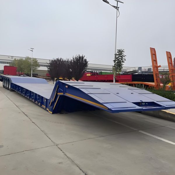
The front-loading arrangement is relevant when machine order, deck access, and available maneuvering room must be planned together.
Final deck position is not the only clearance check
A low machine may fit comfortably after parking but still contact a ramp hinge or deck transition during loading. Therefore, ground clearance, breakover geometry, stabilizers, steps, tanks, and undercarriage components should be considered along the complete loading path.
The second machine makes this more important because maneuvering room becomes limited once the first unit is parked. A correction that would be easy on an empty trailer may become awkward when another piece of equipment occupies the neighboring deck area.
When the proposed sequence requires repeated tight steering, blocked tie-down access, improvised repositioning, or uncertain machine clearance, the arrangement deserves another pass before dispatch.
Verify the Complete Combination Under Local Rules
Heavy-haul limits depend on jurisdiction. Therefore, an axle figure from one country should not be transferred into another load plan. Applicable requirements may govern gross mass, individual axles, axle groups, spacing, tires, width, height, length, overhang, bridges, securement, escorts, permits, and route access.
Private operating sites can add another layer. A combination that is acceptable on a public highway can still face a yard slab, temporary crossing, culvert, ferry ramp, terminal approach, mine road, or construction entrance with different restrictions.
Check the rules against the final arrangement
Machine positions may move several times during planning. Consequently, axle reactions, rear projection, total length, and even transport height can change. Permit information should therefore describe the final loading arrangement rather than the earliest sketch.
The same principle applies after weighing. If either machine moves materially after axle readings are taken, the verified configuration has changed. As a result, the previous reading may no longer describe the dispatched combination.
Several limits can control the same move
Trailer and component ratings, tractor limits, road regulations, permit conditions, bridge restrictions, and route-specific requirements may all set different boundaries. The lowest applicable restriction controls the final load.
There is another practical consequence. A change made to improve axle loading can alter overall dimensions. Moving a long machine rearward may increase overhang. Reversing a unit can move a boom or attachment into a higher part of the transport envelope.
Accordingly, destination-country regulations, road-authority requirements, permit conditions, site procedures, machine instructions, and qualified technical advice should be applied to the final configuration. Where bridge loading, structural adequacy, or axle compliance remains uncertain, specialist review should replace assumptions.
Use a Go/No-Go Worksheet Before Dispatch
By this stage, important information often sits in several places. Machine documents contain weights, a sketch contains positions, scale records contain reactions, and another file contains route restrictions. Therefore, the final decision benefits from one compact worksheet.
The goal is not extra paperwork. Instead, the worksheet should expose unresolved information before the load leaves the yard. A blank critical field should remain a question rather than silently becoming a pass.
1. Both machine weights confirmed
Transport configuration, attachments, loose cargo, fluid condition, and weight sources should match what is actually being dispatched.
2. Both footprints and load centers mapped
The deck plan should show real contact areas, front and rear projections, machine separation, and usable longitudinal center-of-gravity references.
3. Kingpin and axle reactions checked
The chosen positions should remain acceptable for the trailer, tractor, tires, coupling, axle groups, and applicable road limits.
4. Securement and machine clearance workable
Required anchors, restraints, inspection access, loading paths, and machine-to-machine clearances should remain usable after both machines are positioned.
5. Loading and unloading sequence confirmed
Neither machine should trap the other or require uncontrolled maneuvering after the deck becomes crowded.
6. Route and legal conditions closed
Final dimensions, axle arrangement, destination-country rules, permits, route limits, and any required weighing should match the actual dispatch configuration.
Record the positions that were actually approved
Descriptions such as “excavator forward” are useful but difficult to repeat precisely. Instead, the loading record can reference a deck transition, track contact point, distance between machines, rear clearance, and attachment orientation.
Photographs can support those measurements. A useful set may show the complete loaded side profile, both machine positions, trailer axle area, machine-to-machine gap, securement paths, and any tight attachment clearance.
This record becomes particularly useful when the combination goes to a scale. If actual axle readings differ materially from the planning model, the physical machine positions can be compared with the original assumptions instead of relying on memory.
If a machine moves after the combination is checked or weighed, the relevant calculations should be reviewed again. The verified configuration is the one that matters at dispatch.
Low-Bed Configuration
Start With the Real Machine Pair, Not a Generic Payload Number
Axle arrangement, usable deck length, loading method, gooseneck geometry, and securement access should be considered against the actual machinery. Therefore, the BOCA low-bed semi trailer range is best used as a configuration reference after the two machine profiles are known.
A multi-axle layout may suit one project, while a front-loading gooseneck arrangement may solve a different operational problem. Neither choice should be made from axle count or nominal payload alone.
FAQ
The Useful Answer Is a Verified Arrangement, Not a Combined-Weight Total
A two-machine movement becomes workable only when mass and position make sense together. Actual transport weights should feed one deck layout that includes both load centers, both footprints, attachments, securement zones, and practical machine separation.
Afterward, the selected positions should be checked against kingpin reaction, tractor axles, trailer axle groups, structural ratings, dimensions, route rules, and any required permit or weighing process.
- Verify both machines in their actual transport configurations before calculating combined weight.
- Test several realistic front-rear positions rather than accepting the first arrangement that physically fits.
- Stop the release when a critical weight, reaction, clearance, securement, or regulatory condition remains unresolved.
Combined Load Configuration Review
Submit Both Machine Profiles Before the Trailer Configuration Is Locked
Useful project information includes both actual transport weights, overall dimensions, track or wheel footprints, center-of-gravity information where available, installed and detached attachments, and the intended loading order.
The transport file should also include tractor configuration, fifth-wheel information where relevant, trailer axle arrangement, destination country, route restrictions, and available axle or scale data. Those details provide a stronger basis for reviewing an appropriate heavy equipment lowboy configuration.
Most importantly, planning two machines on one lowboy trailer should finish with a defined go/no-go condition for the complete combination. When structural or legal loading cannot be verified, separate movements or qualified technical review remain the appropriate next step.
Submit Machine and Axle Data