
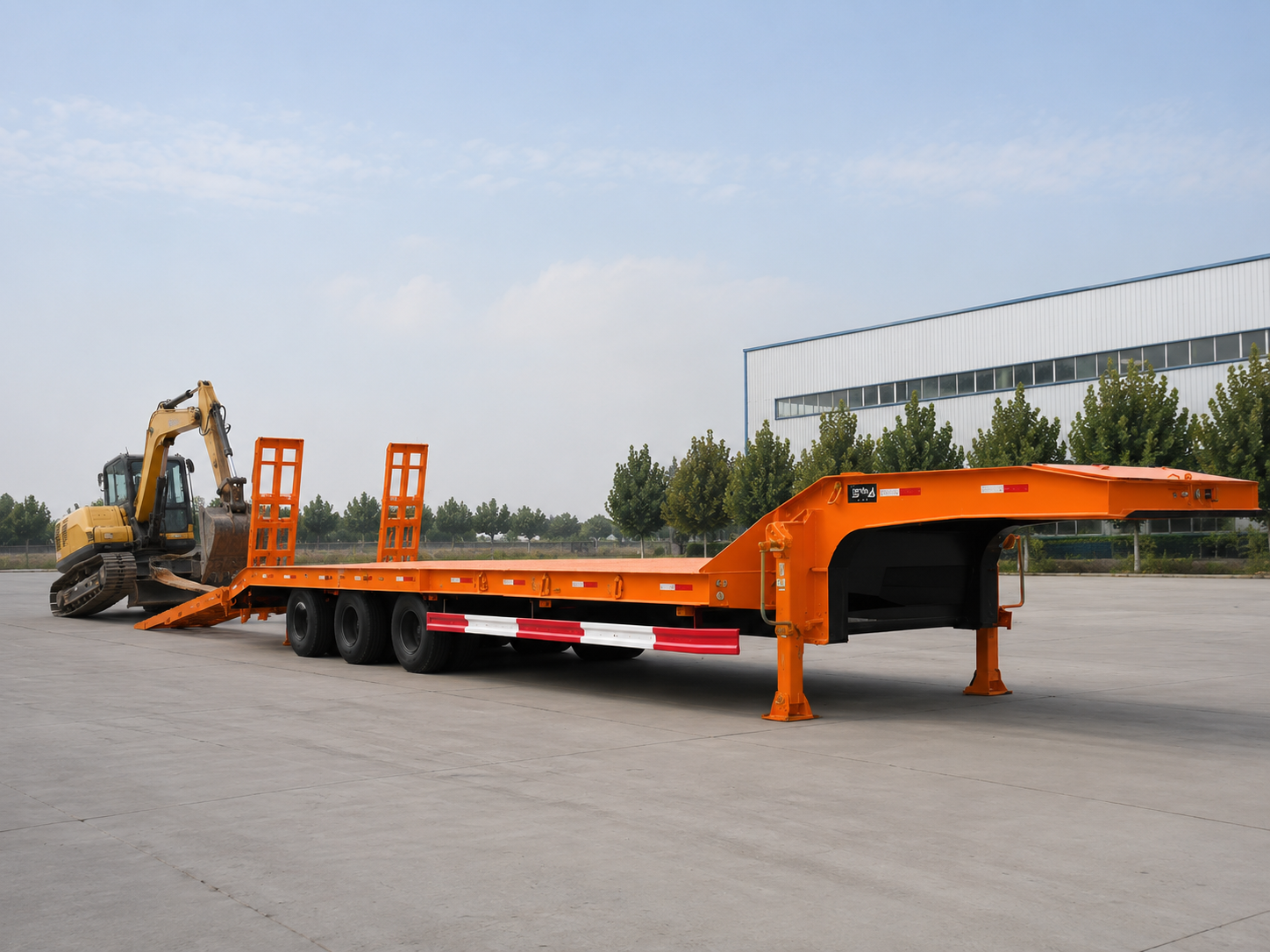
Lowbed Trailer Ramp Angle and Deck Height Guide for Heavy Equipment Loading

A lowbed trailer ramp angle and deck height decision should begin with the machine, not only with trailer capacity. Heavy equipment loading depends on ground entry, ramp surface, hinge transition, deck level, machine undercarriage, attachment position, loading site space, and the intended tractor height.
If these points do not work together, the machine may slip, lose alignment, contact the ramp hinge, damage a low underbody part, or sit too high for the route after loading. Therefore, the best ramp and deck layout should match the real equipment profile, site condition, towing geometry, and destination restrictions.
This guide explains how to compare rear mechanical ramps, hydraulic ramps, and detachable gooseneck / RGN layouts. It also shows what machine data buyers should send before quotation, how deck height affects route clearance, and how excavators, bulldozers, and wheel loaders create different loading risks.
Product Options to Compare
Choose the Loading Layout Around the Machine and Site
The three configurations below represent different loading paths within the lowbed trailer category. Selection should follow machine clearance, loading frequency, available approach space, ground support, towing geometry, and route conditions.
Machine Data
Record working weight, track length or wheelbase, contact width, clearance points, attachment posture, and final transport height.
Loading Geometry
Review lower entry, main incline, ramp width, hinge crest, breakover clearance, and deck transition as one path.
Transport Conditions
Connect deck height with loaded height, axle layout, tractor fifth-wheel height, road clearance, and destination restrictions.
Why Lowbed Trailer Ramp Angle and Deck Height Matter
A ramp may look manageable while the trailer is empty. Once a tracked or wheeled machine starts climbing, the real loading condition changes. The rear of the trailer can move downward, the ramp feet can compress the ground, and a large share of the machine weight may rest on a limited contact area.
The loading path contains three geometric zones. The lower edge controls first contact. The main incline controls traction and stability. The upper hinge controls breakover clearance as the machine moves from the ramp onto the deck.
An acceptable average ramp angle can still hide a sharp local transition. A step, guard, hose, blade bracket, counterweight, ripper, or central underbody component may contact even when the ramp appears long enough. Wet steel, mud, loose stone, worn tires, and polished track shoes can increase the risk at the same time.
Deck height changes the same path. A lower platform reduces the vertical climb and may allow a gentler entry with the same ramp length. It can also reduce the complete transport height and place the machine closer to the road.
However, the lowest possible deck is not always the best solution. Frame depth, axle arrangement, suspension travel, tire position, kingpin height, road clearance, and route quality influence the practical deck level. A layout that helps with overhead clearance may create contact risks on rough access roads or ferry transitions.
Four questions should be answered before selecting a loading system
- Can the front of the machine enter without attachment or underbody contact?
- Will the tracks or tires stay fully supported with enough lateral margin?
- Can the machine cross the upper hinge without breakover contact?
- Will the selected deck height remain practical on the intended route?
Machine Data to Collect Before Planning the Loading Path
Configuration should begin with the machine in its actual working and transport condition. A model name alone may not describe that condition. Buckets, blades, rippers, counterweights, track shoes, tire options, protective structures, and installed tools can change both weight and clearance.
Working Weight and Contact Geometry
Complete working weight provides the starting point, but one total figure cannot describe every loading force. Heavy components may sit near the front, rear, or upper structure. The equipment file should identify installed attachments, removable items, transported tools, and the condition used for the stated weight.
Track length on the ground helps explain how a tracked machine crosses the upper transition. For wheeled machinery, wheelbase serves a similar purpose. When the front support reaches the deck while the rear remains on the ramp, the machine changes pitch and the lowest central component may approach the crest.
Track width, tire width, and outside spacing determine ramp placement. Both inner and outer contact dimensions matter because a ramp can appear wide enough while leaving one edge of a track or tire unsupported.
Ground Clearance, Approach, and Attachment Position
Minimum ground clearance is useful only when its location is known. A machine may have acceptable central clearance but lower steps, hoses, guards, blade frames, or attachment brackets near one end. These points should be measured in the intended loading posture.
Approach, departure, and breakover geometry should be treated separately. An excavator may clear the hinge but bring a low counterweight close to the ground during entry. A bulldozer may clear the center transition but contact the surface with a rear ripper.
Attachment movement should follow the machine manufacturer’s instructions. The trailer layout should support the approved loading posture rather than depend on unusual boom, bucket, blade, or ripper movement to avoid predictable contact.
Transport Dimensions and Site Information
Overall length, width, and height should describe the final transport position. The highest point may be the cabin, exhaust component, protective structure, folded boom, blade, bucket, or another attachment. Route planning should use that confirmed profile rather than a catalogue outline.
The loading site also needs measured information. Surface firmness, available approach distance, side clearance, longitudinal slope, cross slope, drainage, lighting, and nearby obstacles can change the practical loading path.
- Machine model and complete working weight.
- Track contact length or wheelbase.
- Track or tire width and outside spacing.
- Minimum clearance and exact low-point location.
- Attachment type and intended loading posture.
- Transport length, width, height, and highest point.
- Loading-surface type, usable space, and ground slope.
For broader guidance on equipment size, axle layout, deck planning, and trailer selection, read choose a lowbed semi trailer for excavators. This article remains focused on loading path, ramp transition, and deck-height decisions.
Ramp Measurement and Angle Review
Buyers do not need a complicated engineering report before the first quotation, but they do need enough measurements to avoid a wrong loading layout. The most useful starting data are vertical rise, usable ramp length, ramp width, hinge transition shape, deck height, and the machine’s low-point position.
The basic ramp angle discussion should identify the height difference between ground and deck, then compare it with the horizontal ramp length. However, the result is only a starting point. It does not include local steps, hinge crest shape, ground settlement, or how the machine undercarriage crosses the transition.
Confirm the real height from prepared ground to deck entry level under loading conditions.
Use the working ramp surface, not only the total folded ramp structure shown in photos.
Review the hinge crest and machine breakover clearance, especially for long tracked machines.
Soft ground, slope, water, mud, stone, and poor lighting can change the real loading condition.
Simple inquiry data for ramp-angle review
- Deck entry height from ground.
- Usable ramp length and usable ramp width.
- Ramp surface type and lower foot shape.
- Upper hinge height and transition shape.
- Machine low point, track length, and attachment position.
- Loading surface condition and available straight approach distance.
Ramp Length, Hinge Geometry and Breakover Clearance
Ramp length influences the average incline between the ground and the rear platform. When the vertical rise remains unchanged, a longer ramp generally creates a gentler main plane. Length alone, however, cannot confirm that the complete path suits the machine.
Check ramp edge, local step, ground strength, and first contact.
Review slope, usable width, spacing, traction, and alignment margin.
Assess hinge height, crest shape, breakover clearance, and changing support.
Ramp Length Must Fit the Loading Area
A gentler path normally needs more horizontal distance. That distance may not be available inside a narrow yard, port area, mine access road, or construction site. Ramp deployment space and straight machine approach should therefore be measured together.
Longer ramps also need a suitable transport position and locking arrangement. Their mass influences manual handling, spring assistance, hydraulic requirements, and maintenance. A longer design should solve the loading problem without creating an impractical daily routine.
The Lower Edge Can Change on Soft Ground
A thick ramp foot can create a step before the main incline begins. Soft soil can make the condition worse because the edge may sink and rotate after the machine enters. The effective slope then becomes steeper than the unloaded position suggests.
Ground preparation can improve support, but unstable blocks or loose filling materials can introduce new hazards. Any support plate or stabilizing arrangement should follow the agreed operating method and written trailer specification.
Ramp Surface, Width, and Hinge Shape
Patterned plate, bars, mesh, or other traction features may improve grip under defined conditions. Still, surface treatment cannot correct an incline that is unsuitable for the machinery or site.
Steel tracks and rubber tires respond differently to raised surfaces. Mud, oil, water, loose stone, and compacted soil can also change grip. The selected surface should reflect the expected machinery and allow practical inspection and cleaning.
The hinge forms the upper crest. A high or abrupt transition can contact the machine even when the main incline is moderate. A side-profile review should compare the ramp plane, crest shape, deck plane, contact length, and exact low-point position.
Do not compare ramp length alone. A useful quotation should also identify the vertical rise, lower entry shape, usable width, hinge transition, deck level, and the machine profile used for the assessment.
Deck Height, Center of Gravity and Route Clearance
Lowbed trailer deck height affects loading and transport at the same time. A lower platform reduces the vertical climb and may create a gentler entry path. It also lowers the machine within the complete transport profile.
The final platform level must still match the trailer structure. Frame depth, axle arrangement, suspension movement, tire position, kingpin geometry, and road clearance all influence the practical result.
Loaded Height and Route Clearance
Total transport height combines deck level with the highest part of the machine. The cabin, exhaust system, protective structure, boom, bucket, blade, or another attachment may control the final profile.
Route restrictions may include bridges, tunnels, overhead cables, gates, port structures, and site entrances. Local requirements may also involve permits, route approval, escorts, or movement restrictions. These conditions should be confirmed through the responsible local authority or a qualified transport specialist.
Center of Gravity and Under-Trailer Clearance
A lower machine position can support stability, but longitudinal and lateral placement remain important. Machine position affects axle loads, kingpin force, side-to-side balance, attachment clearance, and access to suitable securement points.
A low platform may also reduce clearance beneath parts of the trailer. Rough roads, drainage crossings, ferry ramps, mine entrances, and sudden grade changes can create contact risks. The loaded suspension position should be considered rather than only the unloaded measurement.
Tractor and Trailer Geometry Must Work Together
The towing unit affects trailer attitude, coupling level, turning clearance, braking coordination, and effective deck position. A different fifth-wheel height can raise or lower the trailer front and alter rear loading geometry.
When a used tractor truck will tow the trailer, coupling dimensions, axle arrangement, tire condition, braking and electrical interfaces, expected combination mass, and route gradients should be assessed together.
- The loading path suits the machine’s lowest components.
- The complete loaded height fits the planned route.
- Adequate under-trailer clearance remains available.
- The intended tractor maintains the planned trailer attitude.
Mechanical Ramps, Hydraulic Ramps and RGN Options
Mechanical ramps, hydraulic ramps, and removable gooseneck arrangements solve different operating problems. The right choice depends on machine geometry, loading frequency, deployment space, ground condition, maintenance resources, and preferred loading direction.
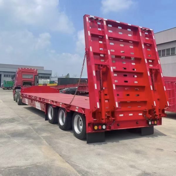
Rear Loading
Mechanical Ramps
Loading is occasional or moderate, the site is controlled, and rear-entry clearance is adequate.
Ramp mass, assistance method, hinge condition, locking, traction, and ground support.
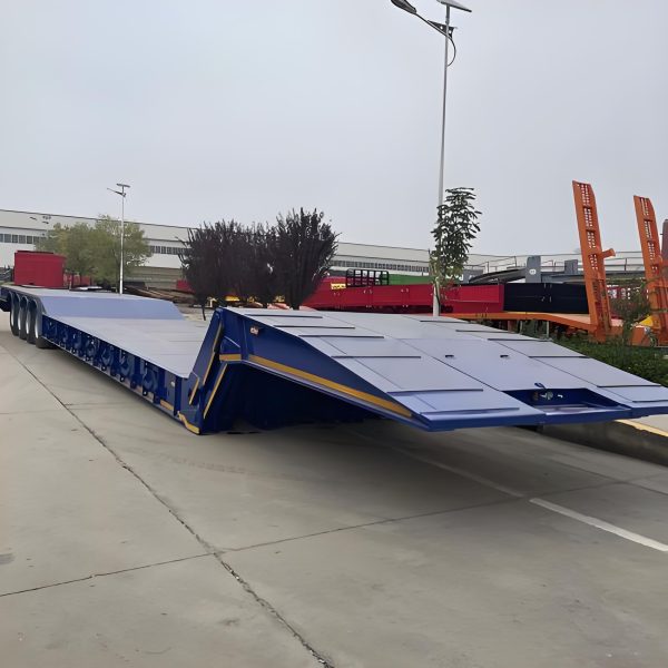
Powered Rear Loading
Hydraulic Ramps
Loading is frequent or the ramp assembly is difficult to deploy manually.
Hydraulic power, hose protection, control position, emergency procedure, and maintenance access.
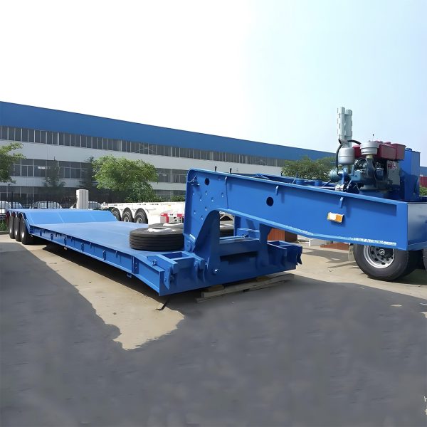
Front Loading
RGN Arrangement
Low-clearance machinery faces difficult rear-ramp or hinge geometry.
Front loading angle, tractor compatibility, ground strength, operating space, and reconnection procedure.
Mechanical ramps may use springs or another assistance arrangement. Their daily usability depends on ramp mass, hinge condition, ground slope, and maintenance. Transport locks, pins, traction surfaces, and support points should form part of regular checks.
Hydraulic ramps can reduce manual handling and support controlled deployment. However, cylinders, hoses, fittings, pins, controls, and the power source introduce additional maintenance points. Powered movement changes how the ramp deploys, not whether its working angle suits the machine.
An RGN arrangement allows machinery to enter from the front after the gooseneck is removed or repositioned. This may reduce some rear-ramp and hinge problems, but site space, ground strength, connection procedure, towing compatibility, and actual RGN loading angle still require review.
Select the loading system around the most difficult machine and the normal operating site. A lighter unit with poor clearance may control the decision more than the heaviest machine in the fleet.
Loading Procedure and Site Safety Checks
A suitable trailer configuration still needs a controlled loading procedure. Machine movement should follow the equipment manufacturer’s instructions, the agreed trailer procedure, and applicable site requirements.
For cargo securement after loading, the official FMCSA cargo securement rules can be used as a reference for heavy vehicles, equipment, and machinery. For loading and unloading safety awareness, OSHA’s loading and unloading guidance is also useful. Local laws, site rules, and destination-market requirements should still be confirmed before operation.
Use firm ground where possible. Remove mud, oil, loose stone, water, and other material that may reduce support or traction.
Apply the specified brakes, wheel restraints, coupling checks, and any confirmed rear-support arrangement.
Check ramps, hinges, locks, pins, traction surfaces, hydraulic parts, and ground contact before entry.
Use one designated spotter. Agree signals before movement and stop if clear communication is lost.
Avoid sudden acceleration, hard braking, and sharp steering. Watch known low points near the upper transition.
Check axle distribution, lateral alignment, attachment position, transport dimensions, and securement access.
Loading should stop if the ramp sinks, twists, moves, or loses even support. The same applies when the machine slips, approaches an edge, nears an unexpected contact point, or loses communication with the spotter.
After positioning and securement, ramps, locks, pins, supports, hydraulic controls, gooseneck connections, lighting, and visible trailer connections should return to the confirmed transport condition.
Matching the Loading Layout to Excavators, Bulldozers and Loaders
Different machine groups place different demands on the loading path. A configuration for several machines should cover a documented operating range rather than rely on a broad phrase such as heavy equipment transport.
Excavators
Long tracks and a low central undercarriage make hinge clearance important.
- Track contact length
- Counterweight clearance
- Boom and bucket posture
- Track width and traction
Bulldozers
The blade and rear ripper can control approach, departure, and side clearance.
- Blade width and position
- Rear ripper clearance
- Track loading
- Straight alignment space
Wheel Loaders
Separate tire contact and articulated steering change the ramp and hinge path.
- Wheelbase and tire spacing
- Central body clearance
- Bucket position
- Straight articulation position
For excavators, track length, undercarriage clearance, counterweight position, and attachment posture usually deserve the closest review. Steel-track traction should also match the expected surface condition.
For bulldozers, blade width and rear ripper position may create limits that are not visible from undercarriage dimensions alone. Side space and initial approach should be checked separately.
For wheel loaders, axle pitch and articulated steering affect the path. The machine should align before entering, and the bucket position should follow the approved loading and transport method.
For mixed operations, prepare a simple equipment list. One machine may control ramp width, another may control breakover clearance, and another may control total loaded height. Equipment outside the agreed range should receive a new assessment.
Quotation Checklist for Ramp and Deck Configuration
A useful quotation request should connect machine dimensions with the loading site, towing unit, and transport route. A short statement such as “for an excavator” leaves critical geometry unresolved.
- Model and working weight
- Transport dimensions
- Contact length and width
- Clearance and low-point location
- Attachments and photographs
- Surface and ground firmness
- Available approach distance
- Side clearance and slope
- Loading frequency
- Space for ramp or RGN operation
- Intended tractor information
- Known loaded-height limits
- Road and site conditions
- Destination country and region
- Local approval responsibilities
Ask for a Configuration, Not Only a Price
The quotation should identify the loading method, ramp arrangement, usable width, transition layout, deck requirement, towing assumptions, and intended machine range. Optional features should be separated from confirmed requirements.
A preference for hydraulic ramps or RGN loading should include the reason. Loading frequency, manual handling, machine clearance, site space, and maintenance capability help determine whether that preference solves the real operating problem.
Avoid These Purchasing Mistakes
- Selecting the trailer only from machine weight.
- Judging the loading path from photographs alone.
- Assuming a longer ramp automatically solves breakover risk.
- Assuming hydraulic ramps automatically create a gentler angle.
- Requesting the lowest deck without describing the route.
- Ignoring the intended tractor and coupling height.
Final dimensions, operating assumptions, optional systems, and inspection points should appear in writing. Changes in machine model, attachment, tractor, loading site, or destination may require a new review.
Boca Vehicle Export and Configuration Support
Boca Vehicle can discuss mechanical ramp, hydraulic ramp, deck, RGN, towing, and export requirements using the submitted machine and route information. Final availability and suitability remain subject to technical review and written confirmation.
The machine list should identify every intended model. One unit may control ramp width, another may control hinge clearance, and another may control loaded height. A broad description cannot provide the same configuration value.
Inspection points can also be agreed before delivery. Depending on the written scope, the review may cover ramp movement, locking, visible dimensions, hydraulic operation where specified, and conformity with the confirmed configuration.
The semi trailer export service page provides more information about service-related support. Destination documents and local compliance requirements should still be confirmed for the intended market.
FAQ
What information is needed to evaluate a lowbed trailer ramp angle?
The main information includes complete working weight, transport dimensions, track contact length or wheelbase, track or tire spacing, minimum clearance, attachment position, and known low points. Surface firmness, approach space, ground slope, and loading frequency should also be included.
How does deck height affect loading safety and route clearance?
A lower deck reduces the vertical climb and can lower the complete transport profile. However, it may also reduce clearance beneath the trailer. Loading geometry, overhead limits, rough-road clearance, suspension movement, and towing-unit height should be reviewed together.
When are hydraulic ramps more suitable than mechanical ramps?
Hydraulic ramps may be more practical when loading occurs frequently or the ramp assembly is difficult to handle manually. They still require inspection and maintenance, and the ramp length, hinge shape, width, and working angle must remain suitable for the machine.
Can one lowbed ramp setup work for different types of heavy equipment?
One setup can serve several machines when every model remains within a documented range for weight, contact width, clearance, attachment profile, and loading geometry. The most difficult machine may not be the heaviest, so each intended model should be checked separately.
Is an RGN always the best option for low-clearance equipment?
An RGN may reduce rear-ramp and hinge problems for some low-clearance tracked machines. However, site space, ground strength, connection procedures, tractor compatibility, maintenance, and the actual front-loading transition still require review.
Can loading geometry be confirmed from photographs alone?
Photographs can show the general ramp style and visible low points, but perspective can make the ramp appear steeper or flatter. Measured ramp length, vertical rise, hinge geometry, deck level, and machine dimensions provide a more reliable basis.
Ramp and Deck Configuration Inquiry
Prepare the Machine Profile Before Requesting a Quotation
The inquiry can include working weight, track length or wheelbase, track or tire spacing, ground clearance, attachment position, transport dimensions, loading-site photographs, intended tractor information, and destination road restrictions.
With that information, the final lowbed trailer ramp angle, transition shape, deck height, loading system, and possible RGN arrangement can be discussed against the actual operating conditions instead of a generic trailer description.
Contact Boca Vehicle for Quotation