
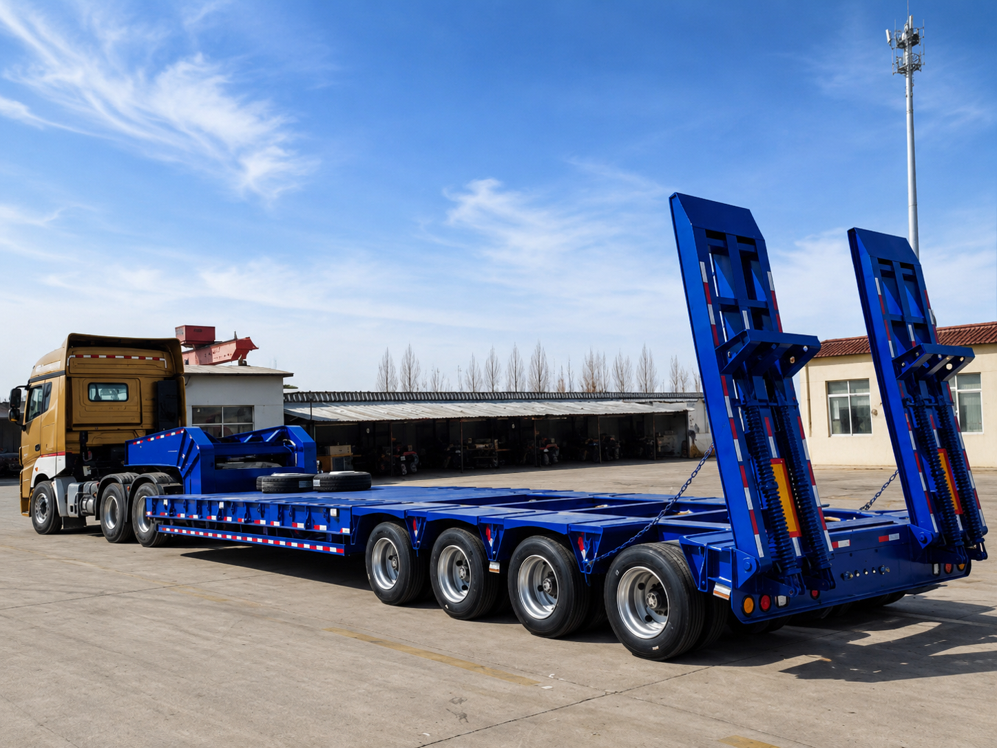
Lowboy Trailer Dimensions and Loading Capacity Guide

A practical guide to deck size, transport height, axle layout, working load, and loading access before a heavy-equipment trailer specification is approved.
Heavy equipment with a similar operating weight can create very different transport demands. A crawler excavator spreads its mass along two tracks, while a wheeled loader or crane may transfer most of the load through a limited number of tires. Long attachments, rear counterweights, low underbody parts, and uneven weight distribution can further change the required platform layout.
Weight alone cannot confirm whether a trailer is long enough, wide enough, low enough, or properly supported. The equipment envelope, deck-contact footprint, loading method, axle reactions, towing unit, and route restrictions should be reviewed as one transport system.
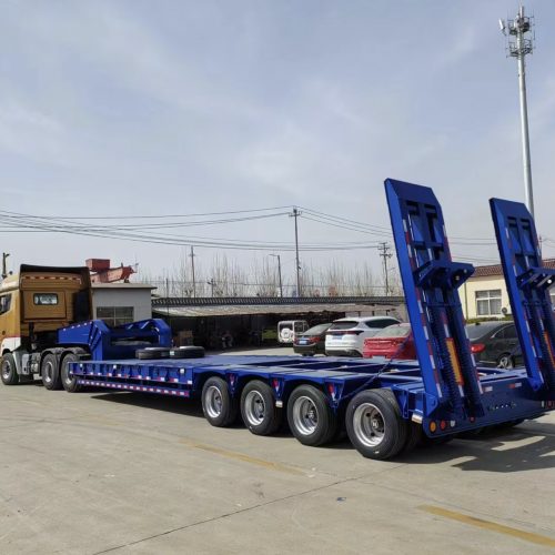
What Lowboy Trailer Measurements Need to Be Confirmed
Machine measurements and trailer measurements describe different limits. Machine data defines the complete transport envelope and the points transferring weight into the deck. Trailer data defines the usable platform, deck transitions, axle position, rear loading structure, and coupling arrangement.
Overall machine length should include every part that remains installed during transport. On an excavator, that may include the folded boom, bucket, counterweight, and any attachment support. A crane, drilling rig, paver, or crusher may have a long upper structure even though its track or tire footprint is relatively short.
Overall width and deck-contact width should be recorded separately. Tracks or tires may fit the platform while a cabin, counterweight, step, blade, or guard projects beyond the deck. Contact width affects platform support, while overall width affects road clearance and possible permit planning.
Transport height should be measured from the surface resting on the deck. Working weight also needs a clear basis. Fuel, buckets, blades, counterweights, tools, transport frames, guards, and later field modifications can change the real load from the standard equipment specification.
Core data for the initial review
- Overall length, width, and height in transport position
- Track, tire, skid, or transport-frame contact dimensions
- Ground clearance and the location of the lowest fixed component
- Working weight, included attachments, and the source of the figure
- Known forward, rearward, or side weight bias
- Loading direction and available loading equipment
- Existing tractor and fifth-wheel information, when available
- Destination country, route conditions, and required quantity
Regional terminology should not replace these measurements. Lowboy, lowbed, low loader, and drop-deck terms may overlap in different markets. The guide to lowboy trailer vs lowbed trailer explains the naming difference, while this article concentrates on dimensional fit, axle arrangement, and working-load information.
Deck Height, Overall Loaded Height and Route Clearance
Lowboy trailer deck height contributes directly to the complete loaded transport height. A machine may fit the platform by length and width yet still conflict with bridges, overhead structures, factory entrances, port gates, utility lines, or route permit limits.
A basic planning figure combines the proposed loaded deck level with the machine height in transport position. Timber blocks, attachment supports, cradles, protective frames, and packing materials may raise the equipment above the platform. Those items should be included rather than treated as minor accessories.
The highest component may not sit near the center of the machine. Exhaust stacks, cabins, folded booms, handrails, warning lights, and guards can create a higher point near the front, rear, or side. Several vertical measurements may therefore be needed.
A lower main deck can provide more overhead clearance. However, it can also reduce clearance beneath the trailer frame. Ferry ramps, road crests, speed humps, steep site entrances, deep ruts, and uneven construction roads may then create underside contact.
Height and load checks must use the same position
The proposed machine location should remain consistent across the height drawing and load-distribution calculation. Moving the equipment forward or rearward changes clearance around the gooseneck and rear platform. It also changes the reactions at the kingpin and axle group.
Removable components can reduce overall height, but their removal adds handling, storage, lifting, and reassembly work. That trade-off should form part of the operating plan rather than appearing only as a drawing adjustment.
Practical height review
Use the proposed working deck level and the actual transport position of the machine. Physical route clearance, road permits, and destination requirements should be checked before the written specification becomes final.
Deck Length and Width Compared with Equipment Footprint
Usable deck size matters more than the total outside length of the trailer. The gooseneck, main deck, rear axle platform, ramp hinges, and loading ramps perform different functions. Only the surfaces intended to carry the machine should be counted as usable platform space.
The deck-contact footprint should be checked at the proposed loading position. Tracks, tires, skids, or transport-frame pads need suitable support. A machine may fit within the outside trailer outline while one contact point sits too close to a deck edge, transition, or unsupported extension.
Attachment support requires separate measurement. A folded excavator boom may need a defined resting point, while a bucket or blade can project beyond the main footprint. Without that information, a platform may appear long enough on paper but remain impractical during loading and travel.
Lowboy trailer deck width should be compared with both the machine contact width and complete road width. Side extensions may be considered when the contact area exceeds the fixed platform. Their structure, support method, operating position, stored position, and destination restrictions should be written into the specification.
A simple top-view and side-view drawing can prevent many quotation errors. The drawing should identify the complete envelope, contact areas, attachment supports, lowest point, approximate center of gravity, and proposed travel direction. Clear reference points matter more than complicated drawing software.
Check the Machine Position Before Approving the Platform
The proposed drawing should show where the machine rests, where its attachments receive support, and how its position affects the gooseneck and rear axle group. A category photograph can support the discussion, but the approved drawing should control the final arrangement.
Axle Quantity, Axle Spacing and Load Distribution
Lowboy trailer axle configuration affects how the working load transfers through the trailer and towing unit. Axle quantity is only one part of the decision. Spacing, suspension behavior, tire arrangement, kingpin position, machine placement, and frame design also influence the result.
Moving the machine forward generally increases the reaction toward the gooseneck and tractor. Moving it rearward generally increases the trailer axle-group reaction. The actual change depends on the usable deck length, axle-group position, and equipment center of gravity.
Attachments can shift this balance even when the base machine remains unchanged. A rear counterweight, front bucket, drilling mast, crane boom, or removable tool may require another loading position. Known side-to-side imbalance should also be stated.
Additional axles may improve load distribution under an agreed design. However, they can also increase overall length, turning space, tire scrub, tare weight, and maintenance demand. A layout suitable for an open highway may be difficult to maneuver inside a port yard, mine entrance, or narrow construction site.
Axle spacing matters as much as axle count
Some routes and jurisdictions evaluate axle groups according to their spacing rather than axle quantity alone. A longer axle arrangement may support one operating requirement but demand more turning room. A compact group may maneuver differently but face another road-load restriction.
Uneven roads can also change how weight is shared between wheels. Deep ruts, cross slopes, loose surfaces, and construction access roads may prevent ideal static distribution. The route description should therefore accompany the theoretical load calculation.
Tractor and fifth-wheel matching
The towing unit should match the expected kingpin load, fifth-wheel height, coupling arrangement, braking interface, and turning clearance. Engine output alone cannot confirm suitability. Driveline condition, rear axle arrangement, gearing, tires, braking, cooling, and road gradients also affect operation.
Fifth-wheel height deserves particular attention. A tractor that sits too high or too low can change trailer attitude, underside clearance, and axle reactions. Gooseneck clearance should also be checked at the expected steering angle rather than only with the combination positioned straight.
Where another towing unit is required, available used tractor truck options can be reviewed against the agreed cargo and trailer data. The tractor and trailer should be treated as one working combination rather than two unrelated purchases.
Rated Capacity vs Actual Working Load
Lowboy trailer loading capacity is often represented by one number. That figure does not explain where the load sits or how it enters the deck. The same total weight can create different structural demands when it is distributed along crawler tracks, concentrated beneath several tires, or transferred through a small number of transport-frame pads.
The quotation should define whether the stated value refers to payload, gross trailer mass, structural design load, or another measure. It should also state whether trailer tare weight, ramps, hydraulic equipment, spare wheels, toolboxes, extension supports, and other options are included.
Machine weight needs the same clarity. Published operating weight may exclude fuel, tools, counterweights, optional attachments, guards, or later modifications. When verified weighing is unavailable, the source of the estimate and any uncertainty should be identified.
Contact pressure can vary along the equipment footprint. Tracks spread weight over a larger area, but rollers and sprockets can create higher local reactions. Wheeled equipment may transfer substantial weight through a limited number of tires, while a transport frame may concentrate the load at several support pads.
Loading conditions should be considered separately from the final travel position. A machine may stop on a ramp, pass over a hinge, or place a concentrated reaction on a transition before reaching the main deck. The loading path can therefore create a different structural condition from the static transport position.
Public-road operation may impose a lower working limit than the structural proposal. Axle-group rules, gross combination limits, bridge restrictions, route permits, tire ratings, and tractor limits can all affect usable capacity. The intended operating environment should be stated before any figure is treated as final.
Treat capacity as a defined working case
The written specification should identify cargo weight, contact pattern, proposed position, axle arrangement, tractor reaction, included trailer equipment, and operating route. An isolated tonnage figure does not provide enough information for a reliable comparison.
Mechanical Ramp, Hydraulic Ramp and RGN Loading Options
Loading access should match equipment mobility, underbody clearance, site conditions, and loading frequency. The preferred arrangement should follow the real operating process rather than the appearance of a previous trailer.
Mechanical Ramp
A straightforward rear-loading arrangement may suit mobile equipment with adequate traction and clearance. Ramp weight, manual handling, loading frequency, rear support, and ground stability still need review.
Hydraulic Ramp
A hydraulic ramp lowboy trailer may reduce manual deployment effort during frequent operation. The system also adds components, operating controls, maintenance needs, service access, and trailer tare weight.
Removable Gooseneck
An RGN lowboy trailer creates a front-loading route after the gooseneck is detached. Ground conditions, connection procedures, tractor compatibility, deck support, and machine clearance remain part of the review.
A machine with low ground clearance may contact a ramp hinge or deck transition even when the main platform is large enough. Track profile, wheelbase, approach geometry, and the exact location of the lowest fixed point should be recorded before the loading method is selected.
The loading surface also matters. A ramp that works on a level paved yard may behave differently on compacted soil, loose gravel, a cross slope, or an uneven mine road. Available working space should be described because front loading and rear loading require different operating areas.
The quotation request should state whether the machine drives, tracks, rolls, winches, or lifts onto the trailer. It should also identify the normal loading direction, loading surface, available support equipment, and expected frequency. Exact ramp geometry and operating procedures should be confirmed for the selected arrangement.
How to Prepare a Dimension and Load Sheet for Quotation
A structured dimension and load sheet reduces repeated clarification and makes several proposals easier to compare. Complex drawing software is not necessary. Clear measurements, labelled reference points, simple diagrams, and useful photographs normally provide a stronger starting point.
A top-view sketch should mark overall length, overall width, contact areas, attachment positions, travel direction, and the approximate center of gravity. A side view should add transport height, ground clearance, contact length, axle or track positions, and the lowest fixed components.
Photographs should support measurements rather than replace them. Front, rear, and side views can reveal projecting steps, folded booms, counterweights, low components, or non-standard modifications that a model number does not show.
Information to include in the quotation file
- Equipment type, model, production year when known, and modification status
- Overall transport dimensions and deck-contact dimensions
- Working weight and the attachments included in that figure
- Center-of-gravity estimate or known front, rear, or side bias
- Loading method, direction, surface, available space, and frequency
- Route type, gradients, bridges, ferries, road surface, and turning restrictions
- Destination country and applicable local review requirements
- Existing tractor, fifth-wheel height, coupling data, and relevant photographs
- Target quantity and requested export, inspection, and shipment scope
When several machines may use one trailer, each machine should have a separate load sheet. The heaviest unit may not be the longest, widest, tallest, or hardest to load. Every proposed machine should be checked against deck fit, transport height, loading access, and axle distribution.
A quotation comparison should also use the same load basis. One proposal may assume transport without a bucket, while another includes all attachments. One may refer to structural payload, while another describes a public-road limit. Those differences should be resolved before price is compared.
Changes to the machine, route, attachments, tractor, or loading method should receive a revision date. Before approval, the proposed trailer drawing should be compared with the latest data sheet line by line. Missing values should become written assumptions or exclusions rather than remaining implied.
Boca Vehicle Configuration Support
Boca Vehicle can review equipment dimensions, working weight, loading method, road conditions, destination country, existing tractor information, and required quantity. This information supports a more focused discussion of the main deck, axle arrangement, loading ramps, removable gooseneck, and towing-unit requirements.
The Boca Vehicle semi trailer manufacturer page provides additional context about manufacturing and configuration support. Each project should still use its own machine, route, and operating data rather than copying a previous arrangement.
A useful proposal should identify the proposed deck dimensions, axle quantity and spacing, suspension concept, tire arrangement, loading method, and main inclusions. It should also show the assumed machine position and explain whether extensions, supports, hydraulic equipment, or a detachable gooseneck form part of the quotation.
Where cargo data remains uncertain, additional drawings or photographs may be requested. This step can prevent incorrect assumptions about attachment support, underbody clearance, contact pressure, and center-of-gravity position. Revised machine information may require another configuration review.
Capacity, materials, certification, destination compliance, export documents, inspection scope, delivery details, and other commercial conditions should remain subject to final cargo information and written agreement. General industry options should not be treated as confirmed project features until they appear in the approved specification.
FAQ
Prepare the Actual Load Data
Confirm the Trailer Around the Equipment and Route
A suitable heavy-equipment transport configuration connects usable deck space, loaded height, axle distribution, tractor matching, and loading access. Each element should be reviewed as part of one complete combination rather than selected separately.
The quotation file should include equipment type, complete transport size, working weight, contact footprint, lowest ground clearance, loading method, road restrictions, destination country, existing tractor information, and target quantity.
With this information, the final lowboy trailer dimensions and working arrangement can be discussed against the intended operation. Unconfirmed capacity, documentation, destination compliance, certification, or delivery terms should not be assumed before the written specification is completed.
contact Boca Vehicle