
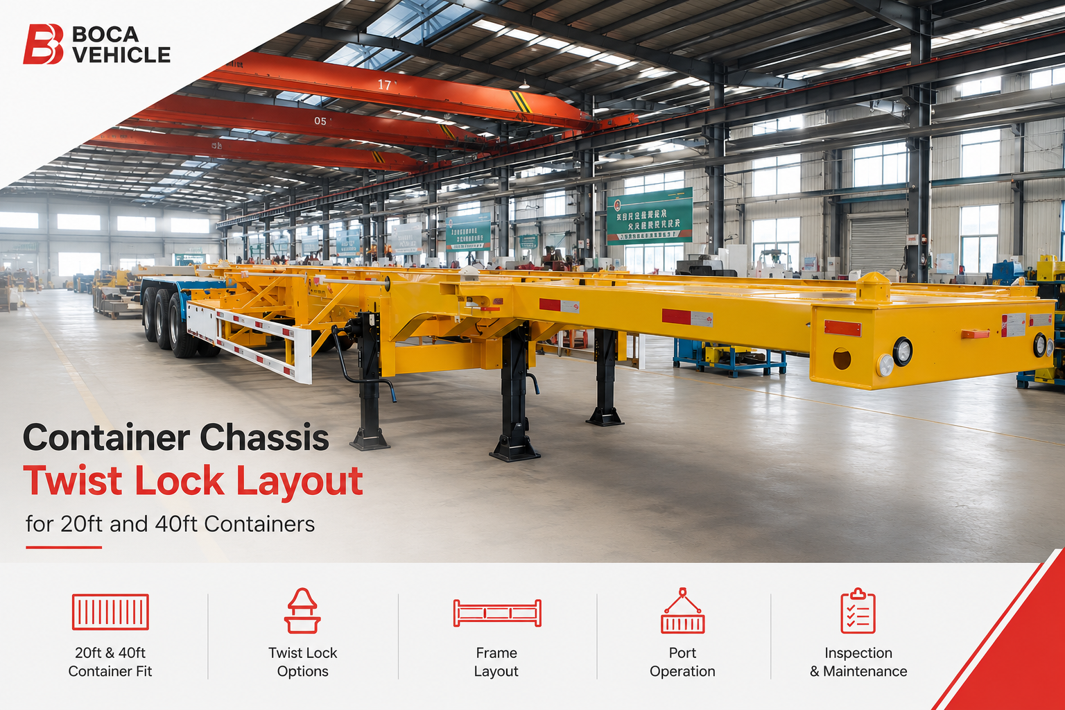
Container Chassis Twist Lock Layout for 20ft and 40ft Containers

Lock position determines where a container sits, how its corner loads enter the skeletal frame, and whether the chassis can handle the intended container combination without awkward terminal procedures. The correct layout must therefore match container length, loading position, axle arrangement, tractor geometry, port equipment, road conditions, and destination requirements.
A container may appear to fit because four locking heads align with four lower corner castings. However, physical alignment alone does not confirm that the frame, kingpin load, axle reactions, inactive locks, or partial-loading condition are suitable. Each permitted operating mode needs its own structural and operational review.
In practice, a suitable container chassis twist lock layout on a container chassis trailer begins with a clear container plan. That plan should state whether the chassis carries one 20ft box, one 40ft box, two 20ft boxes, a conditional 45ft box, or several approved combinations.
This guide focuses on those decisions. It explains where locks may be positioned, when fixed or adjustable arrangements make sense, how frame layout affects load distribution, and what information should be included in a quotation request.
Configuration at a Glance
Four supported corner positions can suit repeated single-container work. The selected box position still needs to match axle and kingpin reactions.
Fixed outer positions can simplify high-frequency 40ft movements. Front turning clearance and rear door access remain important.
Intermediate, folding, retractable, or sliding positions may add flexibility. Every loading combination must be defined separately.
Extended operation requires confirmation of frame geometry, road dimensions, tractor clearance, lighting, and local requirements.
How Container Chassis Twist Locks Secure Standard Containers
Standard containers connect to the chassis through reinforced lower corner castings. During loading, each active locking head enters one casting. The head then rotates beneath the internal retaining surface and limits vertical separation between the container and frame.
Even so, the rotating head forms only one part of the connection. The shaft, housing, handle, retaining parts, mounting plate, cross-member, and main beam must work together. A suitable lock installed on an unsupported or poorly aligned frame position does not create a reliable load path.
Corner alignment
Each active head should enter the intended corner fitting without forced sideways movement.
Vertical support
Container weight should pass through the designed seating areas rather than the rotating shaft alone.
Handle clearance
Tires, guards, toolboxes, suspension parts, wiring, and air lines should not obstruct operation.
Before rotation, the container should settle evenly on the intended support surfaces. Stones, bent brackets, thick coating, frame distortion, or an inactive raised lock can hold one corner above the others. As a result, another locking point may appear incorrectly positioned even when its own assembly remains undamaged.
Forcing a handle under that condition can damage the shaft, housing, retaining parts, or corner casting. Instead, the seating condition should be checked across all four corners. A difficult handle often indicates an alignment or support problem rather than a need for more force.
How the frame receives the corner load
Container reactions enter the chassis at concentrated corner locations. Local mounting plates and cross-members then transfer those reactions into the main longitudinal structure. Therefore, every lock position needs direct support from a suitable frame arrangement.
A new position cannot be created safely by drilling holes in an available frame area without reviewing the load path. The surrounding structure may need additional support, different cross-member placement, or another local mounting arrangement. Exact details should follow the confirmed design and written specification.
Frame stiffness also affects alignment. When a skeletal frame bends or twists, the relative positions of the four heads can change. This issue becomes more visible on uneven ground, during partial loading, or when cargo weight concentrates near one container end.
Loading equipment and temporary misalignment
Port equipment rarely places every box with perfect precision on the first attempt. A crane may lower the container slightly off center, while a reach stacker may create a small side movement during final placement. The chassis should therefore provide clear seating geometry without relying on a lock to pull the box into position.
Small guides and unobstructed support areas can help terminal staff recognize the correct location. However, guides should not create new impact points or prevent the container from sitting fully. The final arrangement must balance loading convenience with structural support and repair access.
During unloading, a stiff or contaminated mechanism can delay container release. In a high-cycle terminal, repeated delays can reduce equipment circulation and encourage rushed handling. Routine cleaning and inspection therefore support operational efficiency as well as connection security.
Key configuration principle: Four matching corner positions are necessary, but they are not sufficient. Frame support, container seating, operating clearance, temporary loading conditions, and final weight distribution must also agree.
Twist Lock Positions for 20ft Container Operations
A dedicated 20ft chassis normally uses four active locking positions aligned with one short container. The larger design question concerns where that box sits on the frame. A rearward position, centered position, or another approved location can create different axle and kingpin reactions.
A rear-positioned box may support certain door-access or loading-dock routines. By contrast, a central position may produce a different balance across the tractor connection and trailer axles. Neither arrangement should be selected only from appearance or general habit.
Information needed before choosing the 20ft position
- Whether one 20ft box forms the normal daily operating condition.
- Whether the container doors need to remain close to the chassis rear.
- Whether dense cargo commonly concentrates near one end.
- Whether the same frame must also carry 40ft containers.
- Whether two 20ft boxes are required on one chassis.
- Whether travel with only one position occupied must be permitted.
Dedicated single-container operation
A dedicated short chassis can use a direct four-position arrangement. Since no alternative container location is required, the skeletal frame may remain mechanically simple. Inspection also becomes easier because every active head serves the same loading mode.
However, the compact frame does not remove the need for load-distribution review. A 20ft container can carry dense cargo within a relatively short floor area. When that weight sits near one end, kingpin or axle reactions may differ substantially from a uniformly loaded box.
The quotation information should therefore describe typical cargo rather than only container length. Machinery, mineral products, industrial parts, general dry freight, and light packaged goods can create different operating conditions. Final limits should follow the approved design and applicable road requirements.
Door direction also affects daily use. Rear-facing doors may simplify warehouse access, seal inspection, or cargo unloading. At the same time, the rear frame, lamps, guards, and lock handles must leave enough working space around the doors.
One 20ft container on a longer frame
A longer chassis may include intermediate positions for one short box. This arrangement can improve equipment utilization when 20ft and 40ft work share the same fleet. Yet the intermediate supports must connect properly to the main skeletal structure.
The selected short-box position may sit near the frame center or another approved location. In either case, unused outer locks should not contact the container underside. Folding, retractable, recessed, sliding, or removable designs may be considered according to the operating frequency.
A central box can leave open frame areas at the front and rear. Those spaces may appear suitable for a spare tire carrier, toolbox, air tank, or other accessory. However, accessory placement must preserve handle clearance, frame movement, and maintenance access.
The position also affects uncoupled loading. When the tractor is absent, the landing gear and trailer axle group support the chassis. A short box placed far forward or rearward may create a demanding temporary reaction during crane or reach-stacker placement.
Two 20ft containers on one chassis
A two-container layout requires four supported corners for each box. The central meeting area becomes especially important because two container ends sit close together. Lock housings, cross-members, handles, and retaining parts need enough space to work without interference.
Counting eight heads does not confirm that the frame suits two-box operation. The central support structure must transfer both container-end reactions into the longitudinal beams. In addition, the arrangement must account for the loading sequence before both boxes are present.
When the first container arrives, one part of the chassis may temporarily carry the full container load. A similar imbalance appears after the first box leaves during unloading. Those temporary conditions may be more demanding than the final fully loaded arrangement.
Travel with only one box may be permitted in some configurations and restricted in others. The remaining box can change steering load, tractor traction, axle distribution, and frame bending. Therefore, each allowed single-box position should appear in the written operating specification.
Both containers occupy their approved positions and all eight corners receive support.
The first box creates a temporary load case before the second container reaches the frame.
The remaining box may need a defined position or a restricted road-movement rule.
Position markings can reduce setup errors. Separate labels may identify front, center, rear, and inactive settings. Color coding can help, but durable text or mechanical indicators should also be present because paint can fade and lighting conditions vary.
A logical 20ft configuration therefore begins with the operating pattern, not the number of locks. Box position, cargo concentration, door direction, partial-loading rules, terminal equipment, and accessory placement should all be confirmed before the final drawing is approved.
Twist Lock Positions for 40ft Container Operations
A 40ft box also connects through four lower corner castings. However, its front and rear support points sit farther apart along the frame. The chassis must therefore transfer loads across a longer skeletal structure while preserving alignment at all four corners.
Where 40ft containers dominate daily work, fixed outer positions can offer a clear operating routine. No intermediate mechanism needs adjustment before each standard loading cycle. Even so, front clearance, rear access, cargo distribution, and frame stiffness still require project-specific review.
Front support and tractor clearance
The front container support often sits near the gooseneck or forward frame area. That relationship affects coupling height and clearance between the container, tractor cab, and chassis structure. Sharp turns, uneven ground, and different fifth-wheel positions can reduce the available space.
Tractor wheelbase, cab shape, suspension, and fifth-wheel location may differ across a fleet. Consequently, a chassis that works with one tractor should not automatically be treated as compatible with every tractor head. Known tractor information should be included during configuration review.
Container underside geometry can also influence the front arrangement. The frame should provide the intended support level without creating unintended contact. Final compatibility should follow the actual container type and agreed dimensional information.
Rear support and container-door access
At the rear, the container position affects door opening, loading-dock access, lighting, mudguards, underrun structures, and license-plate placement. These components should remain outside the active loading path and should not block the lock handles.
A frame that ends too far inside the container outline may complicate dock work or rear inspection. By contrast, an unnecessary extension may affect overall dimensions and terminal maneuverability. The preferred rear relationship should therefore appear clearly on the layout drawing.
Cargo may be unloaded while the container remains on the chassis. Forklift entry, dock plates, and changing internal cargo distribution can alter the support condition during unloading. Operating procedures should account for those changes rather than considering only road travel with closed doors.
Mixed 20ft and 40ft positions
A mixed-use frame often combines outer 40ft positions with intermediate 20ft positions. This arrangement may reduce dependence on separate dedicated chassis. However, the presence of both sets does not confirm every possible loading combination.
The shorter-box position needs its own support structure and load-distribution review. Meanwhile, inactive intermediate heads must stay below or away from the 40ft seating surface. A raised unused component can prevent the longer box from settling evenly.
Folding and retractable locks can reduce that interference. Sliding assemblies can also move between approved positions. Each solution adds different operating steps, inspection points, and maintenance needs, so the preferred method should match the frequency of container changes.
A 40ft chassis should be checked in every intended mode
- One 40ft container on the outer support positions.
- One 20ft container on the approved intermediate position.
- Two 20ft containers where that arrangement is specifically included.
- Temporary partial-loading and unloading conditions.
- All inactive-lock positions beneath each permitted container.
Cargo distribution and high-cube operation
A container may remain within its permitted total mass while carrying more weight near one end. That internal distribution changes reactions across the chassis. Therefore, a frame should not be selected only from the container’s external length or maximum stated mass.
High-cube containers use the same general lower-corner interface, yet overall vehicle height and center of gravity may change. Route clearance, stability, and destination limits need separate confirmation. A suitable lower locking layout does not automatically confirm the full road combination.
Refrigerated containers may also require attention around the front equipment area. Other special units can create different underside clearances or load behavior. Compatibility should follow the identified container type rather than a general statement covering every 40ft unit.
The best 40ft arrangement keeps the main operating position simple while adding only the flexibility that regular work requires. Front clearance, rear access, intermediate-lock control, and realistic cargo patterns should remain central to the final decision.
45ft and Mixed-Container Fleet Considerations
A 45ft arrangement requires more than adding another pair of holes to a 40ft frame. The longer box may change the front or rear relationship between the container, tractor, axle group, lighting, guards, and overall road dimensions.
Market practices and container details can also vary. For that reason, the intended 45ft unit should be confirmed through agreed dimensions or drawings. General claims such as “45ft compatible” are not precise enough for production or destination approval.
Extended frame geometry
Some chassis layouts extend mainly toward the rear. Other arrangements alter the front, rear, or both ends. Each direction changes turning clearance, rear overhang, axle reactions, and empty-chassis behavior in a different way.
An extendable frame may use overlapping beams, locking pins, guide surfaces, stops, or other adjustment parts. These components need visible position confirmation and enough access for cleaning. Dirt or corrosion around a guide can prevent the frame from reaching its intended setting.
Road legality must be considered separately from physical fit. Overall length, rear projection, lighting, markings, underrun structures, and axle distribution may be controlled differently across destinations. Final details should follow applicable requirements and the written vehicle specification.
Avoiding unnecessary fleet complexity
Mixed fleets often request one chassis for every possible container length. Although that goal sounds efficient, unused flexibility can increase empty weight, maintenance work, configuration time, and the chance of operating errors.
The container mix should therefore be ranked by frequency. Where 40ft boxes form most daily movements, the 40ft setting should remain clear and fast. Occasional 20ft or 45ft work can then use secondary positions designed around their actual operating frequency.
A fleet with an even mix may justify a more adjustable chassis. In that case, the operating organization needs suitable training, markings, inspection records, and spare parts. Flexibility creates value only when the supporting maintenance system can manage it.
Keep the outer setting simple. Add shorter or longer positions only where regular work justifies them.
An adjustable system may improve utilization when configuration changes occur throughout the week.
Confirm whether dedicated equipment is more practical than carrying extension hardware on every trip.
Special container types
A mixed fleet may carry dry boxes, refrigerated units, tank containers, platform containers, or other intermodal equipment. Many use standard corner interfaces, but their center of gravity, underside clearance, and accessory position can differ.
Tank containers can introduce liquid movement and a different center-of-gravity condition. Platform units may expose frame components that remain covered beneath a dry box. Refrigerated containers may need additional front-area clearance.
Consequently, approval for a standard dry container should not be extended automatically to every special unit. The exact container construction, cargo, fill condition, road duty, and local requirements should guide the final decision.
Configuration charts for mixed operations
A durable chassis plate or configuration chart can show permitted container lengths, active lock positions, extension settings, and restricted combinations. This information helps terminal staff confirm the setup without relying on memory.
Color coding may support quick identification, but it should not be the only control. Paint can fade, dirt can cover markings, and night operation can reduce visibility. Text labels, mechanical stops, and visible locking pins provide additional confirmation.
The quotation request should therefore avoid the phrase “universal container chassis.” A better specification lists every required box length, loading combination, partial-load condition, extension position, and destination constraint.
Fixed, Sliding and Adjustable Twist Lock Layouts
Lock mechanism selection should follow the real frequency of configuration changes. A dedicated chassis may need only fixed positions. By contrast, mixed operations may benefit from sliding, folding, retractable, removable, or frame-extension solutions.
More adjustment does not automatically create a better chassis. Each moving part adds an operating step and an inspection point. The preferred system should therefore solve a regular fleet problem rather than provide flexibility that rarely receives use.
Fixed twist locks
A fixed unit remains at one defined frame location. This arrangement suits repeated transport of the same container length and position. The local frame can be designed around a known load point, while daily operation remains straightforward.
Fewer adjustment parts may reduce contamination and inspection work. However, the chassis becomes less adaptable when the container mix changes. A dedicated 40ft frame cannot carry a centered 20ft box unless suitable intermediate supports were included in the original design.
Fixed positions are most logical where route contracts, terminal lanes, or container supply remain stable. In that environment, simplicity can support faster setup and easier maintenance. The trade-off is lower flexibility outside the intended duty.
Sliding twist locks
A sliding assembly moves along a defined guide before a pin, latch, or stop secures the selected setting. This method can provide several approved positions without leaving many permanent heads above the frame.
The guide must remain clean enough for reliable movement. Sand, rust, damaged coating, hardened grease, and road debris can restrict adjustment. Accordingly, drainage and cleaning access should form part of the original design.
Position security also needs clear confirmation. A partly inserted pin or worn locking hole can permit unwanted movement. The final setting should therefore be visible and understandable during pre-departure inspection.
Folding and retractable twist locks
Folding or retractable assemblies move between active and inactive positions. Their main advantage is clear seating space when a particular lock set is not required. This can be useful on a chassis carrying both 20ft and 40ft containers.
However, the hinge, shaft, spring, stop, and retaining mechanism need routine checks. An inactive head must remain fully lowered during travel and loading. Vibration should not allow it to rise beneath the container.
A visible active position can also reduce setup errors. Where practical, the mechanism should make an incomplete setting easy to detect. Hidden engagement creates more uncertainty during fast terminal work.
Removable and extendable arrangements
Removable units leave a clear support area after removal. Nevertheless, each loose component needs secure storage, identification, and replacement control. A missing unit can stop the next movement or encourage an unsuitable temporary repair.
Extendable frames create another type of adjustment. They may support several container lengths by changing the chassis geometry rather than only moving the locking heads. The extension pins, overlapping beams, guides, and position indicators then become part of the inspection routine.
Practical mechanism selection
One box length dominates and configuration changes are uncommon.
Several approved locations are used regularly and guide maintenance is available.
Inactive heads must remain below the seating plane without removing loose parts.
Longer-container compatibility justifies the added structure and maintenance work.
Dedicated container transport or multi-purpose freight
Lock layout is also connected to the broader trailer role. A skeletal chassis concentrates material around container support and road-running structure. A flatbed semi trailer provides a full deck for more varied cargo where the approved setup permits container transport.
A dedicated chassis may offer a cleaner container-handling process and fewer unnecessary deck components. A flatbed may suit operations where containers form only part of the freight mix. The decision should follow actual route utilization rather than a general claim that one type is always better.
In most cases, the simplest layout that covers regular operations provides the clearest result. Extra mechanisms should earn their place through frequent use, improved fleet availability, or reduced dependence on separate equipment.
Frame Layout, Tare Weight and Load Distribution
The skeletal frame carries container reactions between the supported corners, kingpin area, landing gear, and axle group. Main longitudinal beams form the primary path. Cross-members, braces, and local plates help distribute concentrated forces around each active position.
A lock should not be placed on an unsupported edge merely because its location matches a container drawing. The frame beneath that point needs enough local support and a suitable path toward the main structure. Lock location and frame design must therefore be reviewed together.
Tare weight without removing necessary structure
A skeletal chassis avoids much of the full loading deck used on a flatbed. This can support a lower empty-weight objective, depending on the final design. However, lightweight planning should focus on efficient structure rather than simple material removal.
Additional container positions often require extra mounting plates, cross-members, guides, hinges, extension beams, or reinforcement. As flexibility increases, tare mass may also increase. The exact effect depends on the approved frame and component arrangement.
A tare target should always appear beside the road and operating conditions. Smooth terminal circulation, long-distance highway transport, rough regional roads, and construction access produce different fatigue and stiffness demands.
The lowest possible empty weight is therefore not a complete purchasing target. A more useful objective balances transport efficiency, frame durability, container flexibility, repair access, and expected service conditions.
How container position changes load distribution
Vertical load divides between the tractor connection and trailer axle group. When a short box moves forward or rearward, that division changes. A centered 20ft container and a rear-positioned 20ft container should therefore be treated as separate load cases.
A 40ft box spreads its support points across a longer frame length, yet the internal cargo can still concentrate near one end. Two containers create another pattern, especially when their cargo weights differ. The final layout should account for realistic operating combinations.
Kingpin reaction is particularly important. Excessive load at the tractor connection may conflict with the intended tractor or road limits. Too little vertical reaction can also affect combination behavior. Exact assessment should follow the agreed tractor, chassis, cargo, and destination requirements.
Load cases that should not be grouped together
- A centered 20ft container with evenly distributed cargo.
- A rear-positioned 20ft container with dense cargo near the doors.
- One 40ft container with cargo concentrated near the front.
- Two 20ft containers with different cargo weights.
- One remaining container after partial unloading.
- A conditional 45ft position with an extended frame.
Landing gear and uncoupled loading
When the tractor remains connected, the fifth wheel supports the front of the chassis. During uncoupled loading, the landing gear replaces that support. The reaction around the landing gear can therefore change according to container position and loading sequence.
A box lowered far forward may create a demanding temporary condition before the tractor reconnects. Likewise, an uneven impact can introduce forces that do not appear in a simple static road calculation. Terminal loading procedures should reflect the approved support condition.
Frame stiffness and loading-area condition
A flexible frame may deflect enough to make one lock difficult to engage. Uneven ground can add torsion before the container reaches the chassis. Since the box remains relatively stiff, the corner positions may no longer align evenly.
Reasonably level loading surfaces reduce this problem. Even so, the frame should tolerate normal operating variation. A chassis that requires perfect yard conditions during every cycle may create repeated delays and unnecessary component damage.
Accessories and exposed systems
Open skeletal construction leaves air lines, electrical wiring, valves, suspension parts, and other systems more visible. That openness improves access, but it can also expose components to road debris or handling impact.
Toolboxes, spare tire carriers, mudguards, air tanks, and storage brackets should be coordinated with the locking layout. A late accessory addition can block a handle, restrict a sliding guide, or interfere with frame movement.
A well-planned frame does not treat locks, axles, landing gear, and accessories as separate purchases. All components should support the same container positions, load cases, inspection routine, and road environment.
Port Handling, Yard Operations and Road Requirements
A chassis may move beneath a crane, beside a reach stacker, through a terminal gate, along public roads, and into a warehouse yard during one transport cycle. Each stage creates different clearance, inspection, and durability requirements.
The locking arrangement should therefore fit the full operation rather than only the final road journey. Rapid terminal handling, frequent coupling, rough access roads, and long outdoor storage can all influence the practical value of a particular mechanism.
Crane and reach-stacker loading
Under crane loading, active positions should remain clear and easy to identify. Inactive heads must not project into the seating plane. A simple visual layout helps terminal staff place the box without studying a complex mechanism during every movement.
Reach stackers commonly approach from the side. Projecting handles, toolboxes, storage brackets, and poorly located accessories may therefore receive impact. The chassis layout should preserve working clearance around the active container corners.
Loading speed should not replace seating checks. A box lowered slightly off center may place side pressure on one head. Correcting the container position is safer than using the handle to pull the casting into alignment.
Yard tractors and frequent coupling
Yard tractors may connect and disconnect many times during a shift. This operating pattern creates repeated impact, vibration, and support changes. Landing gear, electrical connections, air lines, and lock assemblies all experience frequent cycles.
A terminal with dedicated lanes may benefit from simple fixed positions. A mixed terminal may value quick adjustment instead. The correct choice depends on how often container length changes and how much time is available for setup inspection.
Visible handle positions can support gate checks. However, handle direction alone does not prove that a damaged or obstructed mechanism has seated correctly. Inspection should include the head, housing, support surface, and retaining parts.
Public-road operation
Road travel introduces continuous vibration, braking force, turning movement, and frame flex. A final departure check should confirm all active locks and every inactive adjustment component. Extension pins, removable parts, and folded heads also need secure retention.
Front clearance becomes important during sharp turns and on uneven surfaces. Cab shape, fifth-wheel location, wheelbase, coupling height, and container length all affect the available space. The planned tractor and trailer combination should be checked together.
Rear overhang and overall length may be controlled differently across destinations. Conditional 45ft operation therefore requires careful review. Lighting, reflectors, underrun structures, registration details, and route limits should follow the destination requirements.
Legal axle distribution can also restrict a configuration that appears structurally possible. Cargo position inside the box changes the reactions at the tractor and trailer axles. Road suitability should not be determined only from gross container mass.
Road surface, climate, and storage
Smooth port roads create a different fatigue pattern from damaged regional routes or construction access roads. Potholes and twisting surfaces increase frame movement around the support points. The road description should therefore be realistic and specific.
Coastal salt, rain, freezing conditions, dust, and heat can affect lock movement. Corrosion may reduce internal clearance, while excessive grease can collect abrasive dirt. Maintenance methods should reflect the operating environment rather than one general schedule.
Empty chassis may remain outdoors for long periods. Low mileage does not remove the risk of seizure because moisture and debris can collect inside unused mechanisms. Periodic movement checks can identify stiffness before the next loading cycle.
Dedicated chassis or full-deck trailer for container work?
Lock position and skeletal-frame design solve the container-interface question. A separate decision concerns whether the operation needs dedicated container equipment or a full loading deck for mixed freight. The following guide compares those transport roles without replacing the present lock-layout analysis.
Read Container Chassis vs Flatbed TrailerWarehouse and dock operation adds another consideration. Door swing, dock-plate access, rear frame position, and chassis support during unloading can affect daily efficiency. These requirements should be identified before the rear layout becomes fixed.
A suitable port chassis supports rapid handling without ignoring road behavior. Terminal equipment, route limits, tractor geometry, loading sequence, climate, and maintenance capacity should all guide the final configuration.
Inspection and Maintenance Points for Twist Locks
Inspection should begin before the container reaches the chassis. Active heads should move through their intended range, while inactive units should remain secured outside the seating plane. Dirt, stones, rust scale, damaged coating, and hardened grease can all prevent correct operation.
Locking head, shaft, and handle
The head should not show obvious deformation, cracking, severe wear, or impact damage. The shaft should rotate without binding. Meanwhile, the handle should remain firmly attached and should not contact nearby chassis parts.
A stiff handle should not be treated automatically with more force. Uneven container seating, debris, frame twist, or an incorrectly raised inactive lock may be creating side pressure. The cause should be identified before loading continues.
Housing and retaining components
The housing should remain clear enough for the mechanism to move fully. Drainage openings should not be blocked by coating or debris. In dusty conditions, adding grease over contamination can trap abrasive material and accelerate wear.
Pins, clips, nuts, stops, and retaining parts should remain present and secure. A small missing component can allow a larger assembly to move or detach. Improvised wire or unrelated fasteners should not replace the intended retaining method.
Support surface and mounting structure
The seating area around each corner should remain clear and reasonably even. Bent brackets, weld damage, raised coating, or accumulated debris can hold one corner above the others. Another lock may then appear out of position.
Mounting welds and nearby frame areas should receive visual checks. Paint separation, unusual rust lines, visible cracking, or local distortion may indicate movement. Uncertain structural conditions require suitable assessment before further loading.
Sliding, folding, and retractable parts
Sliding units should move to every approved location and lock fully at each setting. Guide surfaces need cleaning, while securing pins and holes should not show obvious damage. Position labels should remain readable after repainting.
Folding or retractable units need secure active and inactive states. Excessive hinge movement can affect alignment. In addition, vibration should not allow a lowered head to rise beneath a container.
Removable parts require controlled storage. Every component should remain available for its intended position. Loose locks left on the frame can be lost, damaged, or become a road hazard.
Before loading
- Confirm the intended container setting.
- Clean every active support surface.
- Check movement, retention, and clearance.
After container seating
- Check all four supported corners.
- Confirm full handle movement.
- Look for raised or uneven seating points.
Before road departure
- Recheck every active connection.
- Secure all inactive adjustment parts.
- Complete the normal vehicle inspection.
Inspection after repairs or impact
Workshop changes can create new interference. A replacement mudguard, lamp bracket, toolbox, air tank, or line route may block handle movement. Every repair should therefore include a functional check in all approved container positions.
Handling-equipment impact may shift a lock position without producing obvious frame damage. If containers suddenly become difficult to seat, frame geometry should be measured. Repeatedly forcing the handles can make the original damage worse.
Replacement work must preserve the intended alignment. A new assembly mounted slightly outside its approved position may continue causing loading problems. Suitable measurements, fixtures, and qualified repair methods should guide the work.
Coating repair also needs care. Thick paint around rotating or sliding surfaces can reduce clearance. At the same time, exposed repaired metal needs protection suited to the operating environment.
Maintenance records can reveal repeated patterns. Frequent damage at one position may point to poor terminal alignment, limited clearance, or a frame issue. Regular seizure may indicate contamination, blocked drainage, or an unsuitable service interval.
Inspection frequency should follow operating intensity and storage conditions. High-cycle port work creates mechanical wear, while long outdoor storage encourages corrosion and stiffness. Both conditions require planned checks.
Quotation Checklist for Container Chassis Buyers
A useful quotation request begins with the container plan. It should identify the primary container length, secondary lengths, required loading combinations, and the frequency of configuration changes. Vague terms such as “standard chassis” or “universal model” do not provide enough information.
Each intended operating mode should appear separately. One 20ft box, one 40ft box, two 20ft boxes, partial loading, and conditional 45ft operation create different frame and load conditions. Combining them into one short sentence can hide important restrictions.
Container and loading information
- Primary container length used most often.
- Secondary lengths and expected operating frequency.
- Required single-container and two-container combinations.
- Preferred position for one 20ft container.
- Permitted partial-load and unloading conditions.
- Required container-door direction and rear access.
- Typical cargo type and likely internal weight concentration.
Partial operation deserves its own written instruction. Where a two-box chassis may travel with only one position occupied, the permitted location should be stated. The loading and unloading sequence should also be described.
Locking and adjustment preference
- Fixed positions for repeated dedicated operation.
- Intermediate positions for mixed 20ft and 40ft work.
- Sliding assemblies for repeated position changes.
- Folding or retractable units for inactive clearance.
- Removable units with a secure storage arrangement.
- Extendable frame requirements for conditional 45ft operation.
Change frequency helps determine the practical mechanism. Several changes during one shift may justify fast adjustment. Occasional changes may favor a simpler manual system with fewer moving parts.
Port, road, and tractor conditions
- Crane, reach-stacker, straddle-carrier, or dock handling.
- Port-only, highway, regional-road, or rough-road operation.
- Approximate trip distance and operating cycle frequency.
- Known tractor wheelbase, fifth-wheel position, and coupling height.
- Preferred chassis axle number and suspension direction.
- Destination requirements affecting dimensions, axle loads, lighting, and registration.
Tractor information helps assess turning clearance and front load. Exact compatibility should follow the intended tractor and chassis combination. A generic tractor description may not identify an unusual fifth-wheel position or cab-clearance issue.
Frame and accessory priorities
- Target balance between empty weight and operating durability.
- Road quality and expected environmental exposure.
- Toolboxes, spare tire carriers, tanks, guards, and storage brackets.
- Required configuration labels or position plates.
- Access requirements for cleaning, inspection, and replacement.
- Packing, shipment, inspection, and documentation expectations.
A lightweight target should not appear without operating context. The same target may suit smooth terminal roads but conflict with rough long-distance duty. Frame efficiency, stiffness, service conditions, and repair access should be discussed together.
Accessories should be included before the layout becomes final. A toolbox or spare tire carrier added later can block a handle or sliding guide. Early coordination reduces avoidable fabrication changes.
Replace vague wording with a usable configuration request
Avoid phrases such as “all container sizes,” “standard port model,” or “universal chassis.”
Instead, list the exact box lengths, loading positions, adjustment method, partial-load rules, road environment, axle preference, tractor details, accessories, and destination requirements.
Documentation expectations should also be agreed before ordering. Depending on the project, the final package may include configuration drawings, operating guidance, inspection records, packing details, and export documents. The exact scope should follow the written agreement.
Boca Vehicle can review container combinations, operating conditions, chassis form, inspection needs, and shipment planning under the agreed project scope. The available semi trailer export service provides a starting point for configuration, inspection, packing, and delivery discussions.
A complete request does not need to contain every engineering answer. However, it should describe the actual transport task clearly enough for all open points to be resolved before the final production drawing is approved.
Match the chassis starting point to the regular container mix
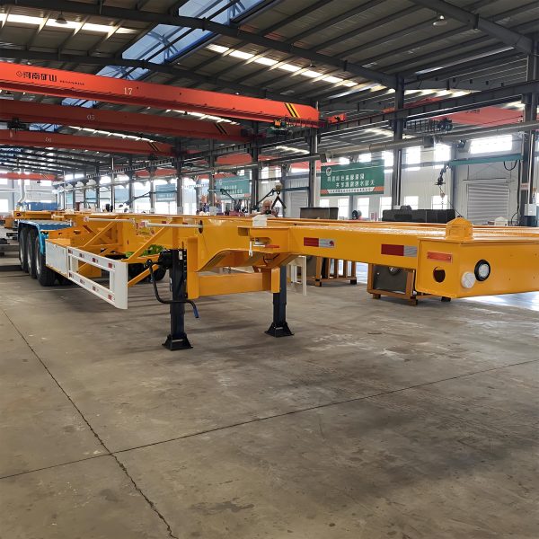
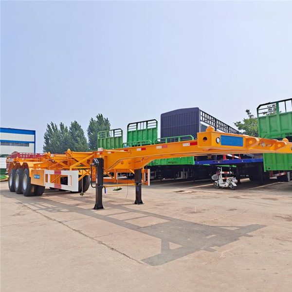
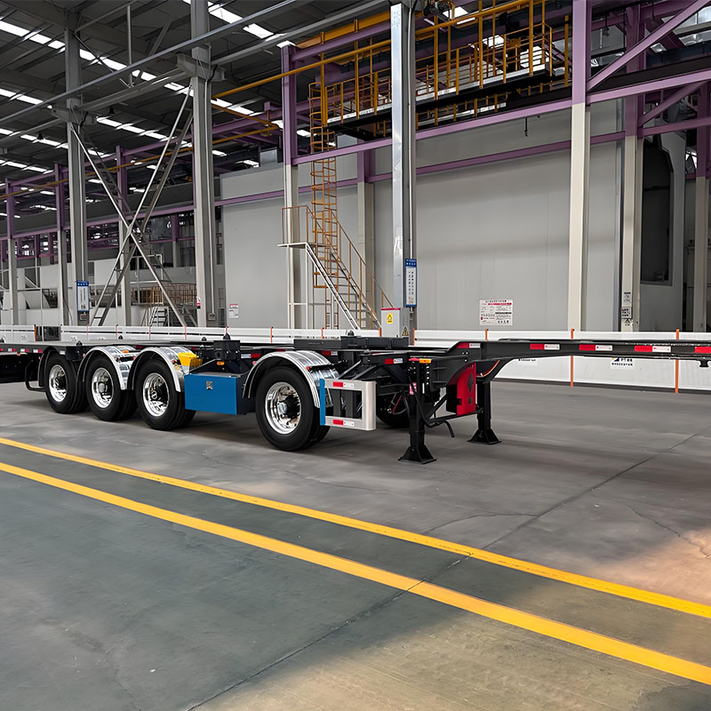
The following product pages provide relevant starting points for dedicated 20ft, standard 40ft, and conditional 45ft projects. Final lock positions, axle arrangement, frame details, and destination requirements should still be confirmed through the written quotation.
FAQ
How are twist locks arranged for a 20ft container chassis?
A dedicated short chassis normally uses four supported positions aligned with the lower container corners. The box may sit near the rear, closer to the center, or at another approved position according to the frame and load-distribution plan.
On a longer chassis, intermediate supports may carry one 20ft box. Two-box operation requires eight supported corners, a suitable central frame area, and confirmation of partial-loading conditions.
Can one chassis carry both 20ft and 40ft containers?
A purpose-designed frame can include outer positions for a 40ft box and intermediate positions for one 20ft box. Folding, retractable, removable, or sliding arrangements may keep unused heads away from the seating surface.
Physical lock alignment is not enough. Frame support, axle reactions, kingpin load, inactive-lock clearance, tractor compatibility, and permitted partial conditions also require confirmation.
When are sliding or adjustable twist locks useful?
Adjustable systems are useful when approved container positions change regularly. They can improve fleet utilization and reduce dependence on separate dedicated chassis.
However, guides, pins, hinges, stops, and retaining parts add maintenance work. The mechanism should match the change frequency, terminal environment, inspection capacity, and available cleaning access.
What should be inspected before loading a container onto the chassis?
Active heads should move freely and show no obvious deformation, severe wear, or impact damage. Housings, shafts, handles, retaining parts, support surfaces, and nearby frame areas also need inspection.
The selected positions should match the intended container length. Inactive units must remain secured, and all container corners should sit evenly before the handles are rotated.
Final Configuration Priorities
A reliable layout begins with a precise container plan rather than a request for maximum flexibility. Fixed positions suit stable duties, while adjustable systems can support changing container lengths. Every additional position also affects frame structure, empty weight, inspection work, and operating procedure.
Temporary conditions deserve the same attention as normal road travel. Partial loading, unloading order, uneven ground, tractor geometry, and concentrated cargo can change chassis reactions significantly.
- List every required container combination, including single-box and partial-load positions.
- Describe the real operating environment, including port equipment, road quality, tractor arrangement, and destination rules.
- Confirm the final drawing in writing, including active locks, inactive positions, frame form, accessories, and maintenance access.
Confirm the container positions before finalizing the chassis
A project-specific container chassis twist lock review should include the regular container lengths, mixed-loading requirements, port conditions, road environment, axle preference, lightweight objective, tractor information, and destination requirements.
Contact Boca Vehicle